Axial permanent-magnet motor

A permanent magnet motor, axial technology, used in motors, synchronous motors with stationary armatures and rotating magnets, electric vehicles, etc., can solve the problems of large stator yoke, low coil filling factor, affecting motor power, etc. , to increase the filling density, optimize the magnetic field distribution, and reduce the iron loss.

Inactive Publication Date: 2018-02-09
HEFEI UNIV OF TECH
View PDF5 Cites 4 Cited by
  • Summary
  • Abstract
  • Description
  • Claims
  • Application Information

AI Technical Summary

Problems solved by technology

The axial permanent magnet synchronous motor with inner stator and outer rotor structure will cause a larger stator yoke volume, which will cause higher losses; the axial permanent magnet motor with an outer stator and inner rotor structure will cause a lower fill factor of the coil, so will affect the power of the motor

Method used


Image

  • Axial permanent-magnet motor
  • Axial permanent-magnet motor
  • Axial permanent-magnet motor

Examples


Embodiment 1

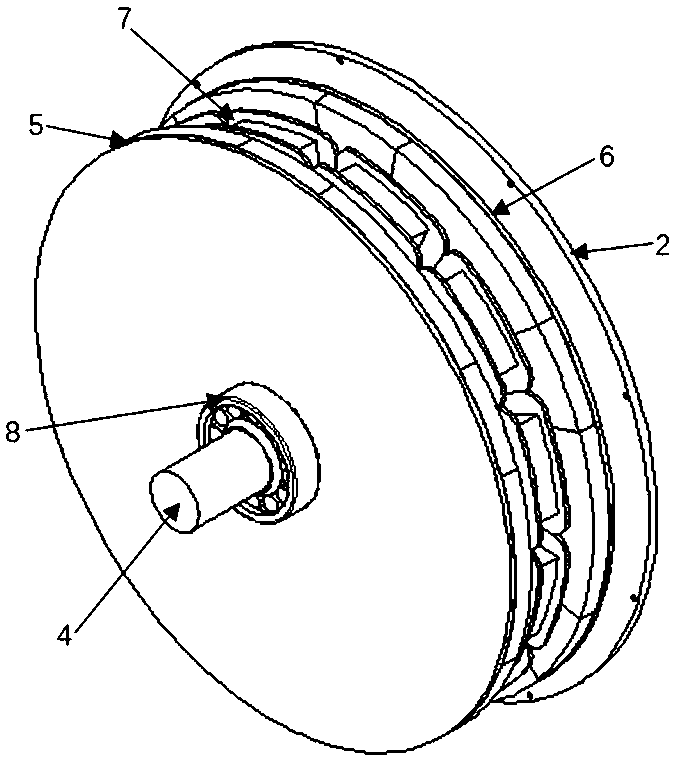
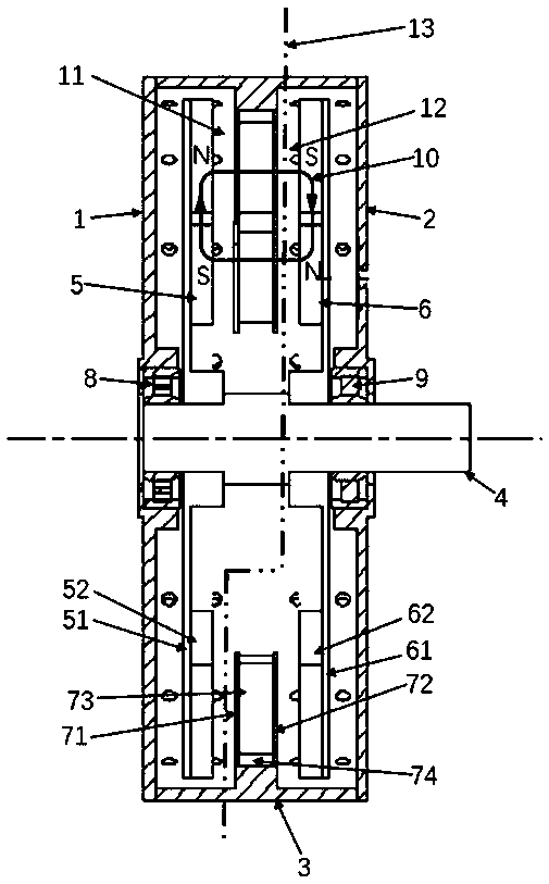
[0035] see figure 2 , an axial permanent magnet motor includes an annular casing 3, a stator 7, a first rotor 5, a second rotor 6 and a rotating shaft 4; the stator 7 is coaxially installed in the axial middle of the casing 3; the rotating shaft 4 passes through The axial middle part and both ends of the stator 7 are rotatably mounted on the casing 3 through bearings. The first rotor 5 and the second rotor 6 are mirror-symmetrically mounted on the rotating shaft 4 on both sides of the stator 7, and rotate with the rotating shaft 4; the magnetic circuit formed is: starting from the first magnet of the first rotor 5, passing through The first coil of the stator 7 enters the first magnet on the second rotor opposite to the first magnet of the first rotor, passes through the iron core of the second rotor, enters the second magnet of the second rotor, and passes through the stator and the first magnet. The second coil adjacent to the coil enters the second magnet on the first rot...

Embodiment 2

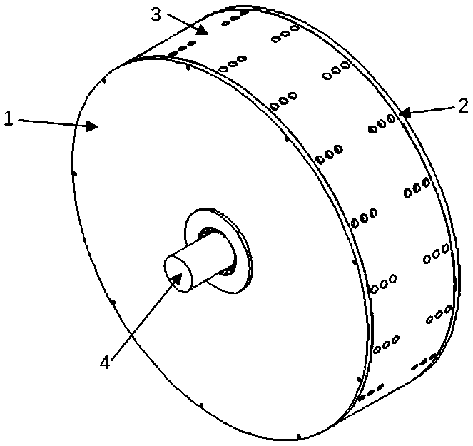
[0048] see figure 1 , when the motor is used in a place that does not need to be sealed, cooling holes are evenly distributed on the circumference of the casing 3, which improves the cooling effect of the motor.

[0049] The outer diameter of the stator 7 is 100 mm, and the axial distance between the first permanent magnet 52 or the second permanent magnet 62 and the stator 7 is 3 mm.

[0050] In the present invention, the number of stator coils and the number of permanent magnets of the rotor may be different, for example, 12 stator coils correspond to 10 permanent magnets of the rotor. In this way, it can be guaranteed that the stator coil will not be in the same position as a certain permanent magnet at any time, and it can be ensured that energizing the motor at any time and any position can generate torque rotation.


PUM


Abstract

The invention proposes an axial permanent-magnet motor structure. The axial permanent-magnet motor structure is characterized in that the motor is integratedly in a disc shape, a distribution mode ofdual rotors and an intermediate stator is employed, a magnetic flux direction is an axial direction, the two rotors rotate around the same rotation shaft, axial positions are fixed by end covers at positions, near to outer sides, of the two rotors and the rotation shaft, permanent magnets are arranged at inner sides of the rotors in a halbach form, the intermediate stator employs a yoke-free structure and is a formed in which multiple teeth are combined, the stator is fixed on an enclosure, and the enclosure is connected and fixed with the two end covers. Structure topological optimization isperformed on the enclosure, ventilation holes are formed in a surface of the enclosure, and heat dissipation of the motor is facilitated. Therefore, the axial permanent-magnet motor has the advantagesof small volume, small mass and high power density, and is applicable to occasions such as an electric vehicle and an aircraft. The invention further provides a rotor-free core structure design, andthe power density of the motor is further improved.

Description

technical field [0001] The present invention proposes a new type of axial permanent magnet motor, which adopts the arrangement of double-rotor intermediate stators, which includes a stator and a rotor that is supported by a rotating shaft and rotates around the stator. This rotor generates a magnetic field that passes through the space between the stator and rotor and interacts with the magnetic field generated by the stator windings to generate torque. To be precise, it is an axial permanent magnet motor involving a permanent magnet rotor in the form of a double-layer halbach and a yokeless segmented stator structure. Background technique [0002] At present, there are many types of motors on the market, each of which has its own shortcomings. Most motors have the disadvantages of large volume, low power density, and complex structure. [0003] Compared with other motors, the permanent magnet synchronous motor has the characteristics of simple structure, small size, light...

Claims


Application Information

Patent Timeline
Patent Type & Authority Applications(China)
IPC IPC(8): H02K16/02H02K21/24
CPCH02K16/02H02K21/24H02K2213/03Y02T10/64
Inventor 赵韩李晨鸣黄康孙浩甄圣超朱胤斐
Owner HEFEI UNIV OF TECH
Why Eureka
Try Eureka