Three-dimensional scanning system based on structured light

A technology of 3D scanning and structured light, which is applied in the field of 3D perception, can solve the problems of no revolutionary technological update, 3D scanning system cannot be matched arbitrarily, and limited user experience improvement, so as to reduce stuttering and heat generation, reduce Parallax, the effect of sharing resource consumption

Pending Publication Date: 2018-02-09
SUNNY OPTICAL ZHEJIANG RES INST CO LTD
View PDF0 Cites 8 Cited by
  • Summary
  • Abstract
  • Description
  • Claims
  • Application Information

AI Technical Summary

Problems solved by technology

The most representative array camera is the dual camera, which is already a standard configuration of high-end models on many mainstream brand mobile phones. Bringing Revolutionary Technology Updates
The existing three-dimensional scanning system based on structured light has poor versatility and limited application range
For different products, the existing three-dimensional scanning system based on structured light cannot be matched arbitrarily or function normally
In addition, the existing 3D scanning system has a single structure and arrangement, and does not have high precision.

Method used


Image

  • Three-dimensional scanning system based on structured light
  • Three-dimensional scanning system based on structured light
  • Three-dimensional scanning system based on structured light

Examples


Embodiment 2

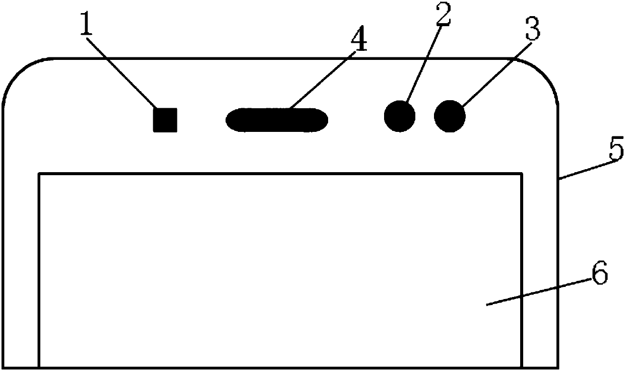
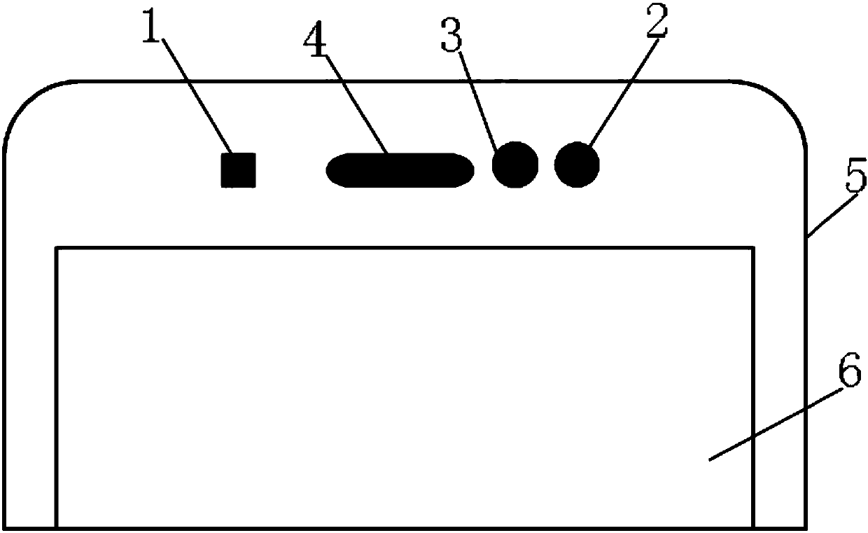
[0046] like Figure 10 As shown, based on Embodiment 2 of the second technical solution of the present invention: the mobile phone screen 6 is embedded in the mobile phone shell 5, and the earpiece 4 is arranged at the middle position of the mobile phone shell 5 positioned at the top of the mobile phone screen 6 . Two infrared cameras 2 are arranged on both sides of the earpiece 4 respectively, and the color camera 3 is arranged between the earpiece 4 and the infrared camera 2 on the right side of the earpiece 4 , and is arranged next to the infrared camera 2 . The infrared projector 1 is arranged between the earpiece 4 and the infrared camera 2 on the left side of the earpiece 4, and the distance between the infrared projector 1 and the infrared camera 2 on the right side of the earpiece 4 is 15-30mm.

[0047] Of course, based on the above-mentioned second embodiment of the present invention, there can also be other embodiments. For example, when the infrared projector 1 and ...

Embodiment 1

[0056] like Figure 11 As shown, embodiment 1 based on the above-mentioned technical solution of the present invention: in this embodiment, the infrared projector 1, the infrared camera 2 and the color camera 3 are all arranged in the casing 4 of the camera, and the infrared projector 1 is in the casing 4 is set to the right, the infrared camera 2 is set to the left in the housing 4, and the distance between the infrared projector and the infrared camera 2 is 15-30mm. The color camera 3 is located between the infrared projector 1 and the infrared camera 2, and is arranged next to the infrared camera 2. A USB interface 5 is provided on one side of the housing 4 , and the camera module made by the structured light-based three-dimensional scanning system of the present invention can be connected to a mobile phone through the USB interface 5 . Of course, when only one infrared camera 2 is provided in the present invention, the arrangement of the infrared projector 1, infrared cam...


PUM


Abstract

The invention relates to a three-dimensional scanning system based on structured light. The system comprises an infrared projector for projecting an infrared laser pattern to a target object; at leastone infrared camera for shooting the target object attached with the infrared laser pattern, and generating an infrared image; a depth computing chip electrically connected with the infrared camera and used for computing and outputting the depth data of the infrared image transmitted through the infrared camera, and further comprises a color camera; and a processor electrically connected with theinfrared projector, the infrared camera, the depth computing chip and the color camera. The three-dimensional scanning system based on structured light is flexible in structure, extensive in application range and good in universality when the high precision is guaranteed.

Description

technical field [0001] The invention belongs to the technical field of three-dimensional perception, and in particular relates to a structured light-based three-dimensional scanning system for mobile phones. Background technique [0002] Three-dimensional sensing technology is a technology that increases the distance information in the depth direction on the basis of traditional two-dimensional images, so that it can measure three-dimensional information in space. The application of 3D perception technology on mobile phones can be roughly divided into array camera, time-of-flight method and structured light. The most representative of the array camera is the dual camera, which is already a standard configuration of high-end models on many mainstream brand mobile phones, but the technology itself has the defect of low reliability of the algorithm, which brings limited user experience improvement Bringing revolutionary technological updates. The existing three-dimensional sc...

Claims


Application Information

Patent Timeline
Patent Type & Authority Applications(China)
IPC IPC(8): H04N13/268H04M1/02G01B11/25G01J5/00
CPCG01B11/2518G01J5/00G01J2005/0077H04M1/0264
Inventor 张康铎龚艳芸周炳刘富春胡增新葛晨阳
Owner SUNNY OPTICAL ZHEJIANG RES INST CO LTD
Why Eureka
Try Eureka