Method for measuring width of subsurface defect based on laser ultrasonic surface waves

A sub-surface defect, laser ultrasonic technology, applied in the direction of using ultrasonic/sonic/infrasonic, using sound/ultrasonic/infrasonic to analyze solids, using sound/ultrasonic/infrasonic for material analysis, etc., to avoid secondary clamping and complicated equipment , the effect of simple method

Active Publication Date: 2018-02-13
ZHEJIANG UNIV
View PDF5 Cites 16 Cited by
  • Summary
  • Abstract
  • Description
  • Claims
  • Application Information

AI Technical Summary

Problems solved by technology

[0005] The purpose of the present invention is to overcome the time-consuming caused by the secondary clamping of the workpiece in other measurement systems in some occasion

Method used


Image

  • Method for measuring width of subsurface defect based on laser ultrasonic surface waves
  • Method for measuring width of subsurface defect based on laser ultrasonic surface waves
  • Method for measuring width of subsurface defect based on laser ultrasonic surface waves

Examples


Embodiment Construction

[0026] The present invention will be specifically described below in conjunction with the accompanying drawings and embodiments.

[0027] The embodiment of the present invention relates to a method for detecting the width of subsurface defects based on laser ultrasonic surface waves. By receiving and calculating the incident surface wave signal and the scattered echo signal, the width of the subsurface defect of the workpiece can be detected.

[0028] The basic principle of the detection method of subsurface defect width based on laser ultrasonic surface wave of the present invention is partly consistent with the content of the invention, and the specific steps are as follows:

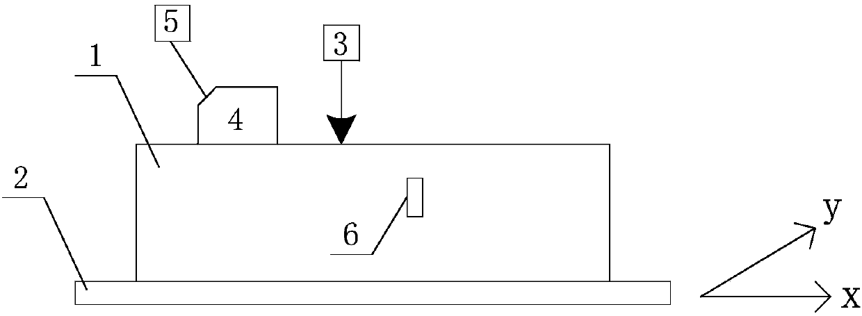
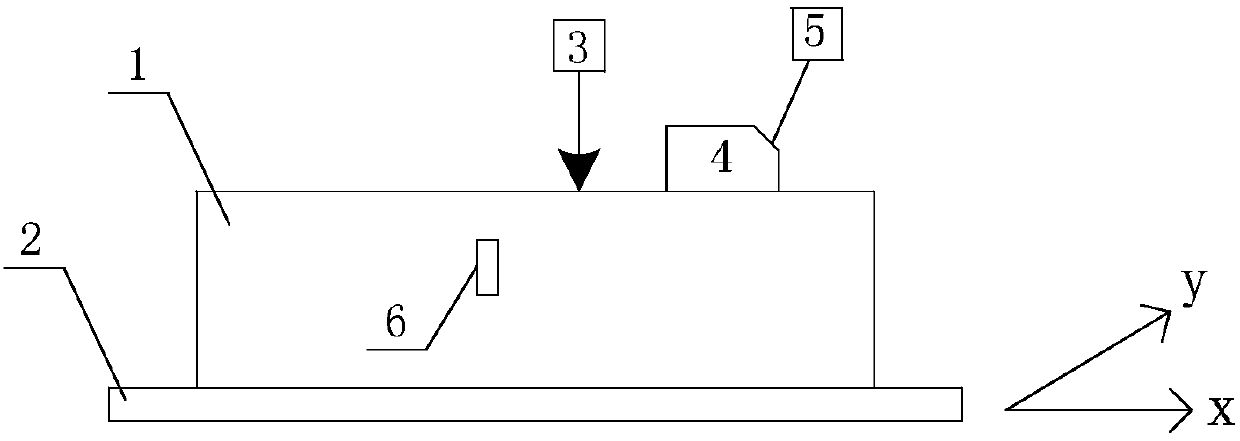
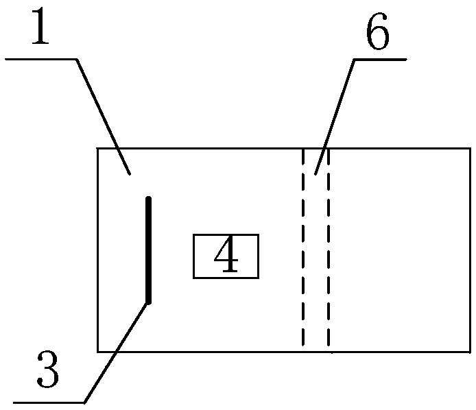
[0029] 1) Place the workpiece 1 with the surface defect 6 on the two-dimensional motion platform 2 so that the long side and the short side of the workpiece are respectively parallel to the two moving directions of the two-dimensional motion platform 2; place the pulse laser probe 3 and the ultrasonic ...


PUM

PropertyMeasurementUnit
Thicknessaaaaaaaaaa

Abstract

The invention discloses a method for measuring the width of a subsurface defect based on laser ultrasonic surface waves. The method comprises the following steps: (1) a pulsed laser probe and an ultrasonic probe are placed on one side of the subsurface defect of a workpiece, and pulsed laser is located between the subsurface defect and the ultrasonic probe; (2) a pulsed laser device excites surface acoustic waves on the surface of the workpiece, and the ultrasonic probe detects a direct surface wave signal R1 and a surface wave signal RR1 reflected by the defect; (3) the ultrasonic probe is taken down, a two-dimensional displacement platform is controlled to move, the pulsed laser is located on the other side of the subsurface defect, the ultrasonic probe is placed, and the pulsed laser islocated between the subsurface defect and the ultrasonic probe; (4) the step (2) is repeated, and the ultrasonic probe detects a direct surface wave signal R2 and a surface wave signal RR2 reflectedby the defect; and (5) in accordance with the reaching time of the direct surface wave signal and the defect echo signal, which is twice measured by ultrasonic probe, the movement displacement d of the three-dimensional movement platform and a surface wave echo time compensation factor alpha, the width of the subsurface defect is calculated. The method can be used for on-line measurement, and canaccurately measure the widths of subsurface defects with different depths and internal shapes.

Description

technical field [0001] The invention relates to the field of nondestructive testing, in particular to a method for measuring the width of subsurface defects based on laser ultrasonic surface waves. Background technique [0002] Subsurface defects are tiny defects with a depth ranging from a few microns to hundreds of microns, and defect sizes ranging from a few microns to tens of microns, produced during ultra-precision machining such as fine grinding and polishing. Because it is not on the surface of the workpiece and is very small, it is not easy to detect by conventional methods. In the process of use, subsurface defects will pose a great threat to the safe operation of equipment, and may also cause serious consequences, such as equipment failure, safety accidents and serious economic losses. For this reason, many scholars have devoted themselves to researching methods for detecting subsurface defects. [0003] In the existing research, Balogun et al. have developed a s...

Claims


Application Information

Patent Timeline
IPC IPC(8): G01N29/04G01B17/00
CPCG01B17/00G01N29/041G01N2291/0423
Inventor 居冰峰王传勇孙安玉孙泽青朱吴乐薛茂盛
Owner ZHEJIANG UNIV
Why Eureka
Try Eureka