
High-voltage side grid driving circuit for half-bridge structure

A gate drive circuit, high-voltage side technology, applied in the high-voltage floating gate drive circuit, high-voltage drive field, can solve the problem of anti-VS negative bias capability and channel transmission delay can not be considered, small transmission delay and other problems, to overcome the resistance to dV /dt effect of noise capability

Active Publication Date: 2018-02-13
SOUTHEAST UNIV +1
View PDF4 Cites 6 Cited by
  • Summary
  • Abstract
  • Description
  • Claims
  • Application Information

AI Technical Summary

Problems solved by technology

[0007] Aiming at the problem that the anti-dV / dt ability, anti-VS negative bias ability and channel transmission delay cannot be taken into account in the existing technology of the high-voltage side gate drive circuit, the present invention proposes a high-voltage side gate drive circuit for a half-bridge structure , the pulse filter circuit used in it has high anti-dV / dt noise ability and anti-VS negative bias ability, and the channel has a small transmission delay, and the circuit structure is small, saving the layout area

Method used


Image

  • High-voltage side grid driving circuit for half-bridge structure
  • High-voltage side grid driving circuit for half-bridge structure
  • High-voltage side grid driving circuit for half-bridge structure

Examples


Embodiment Construction

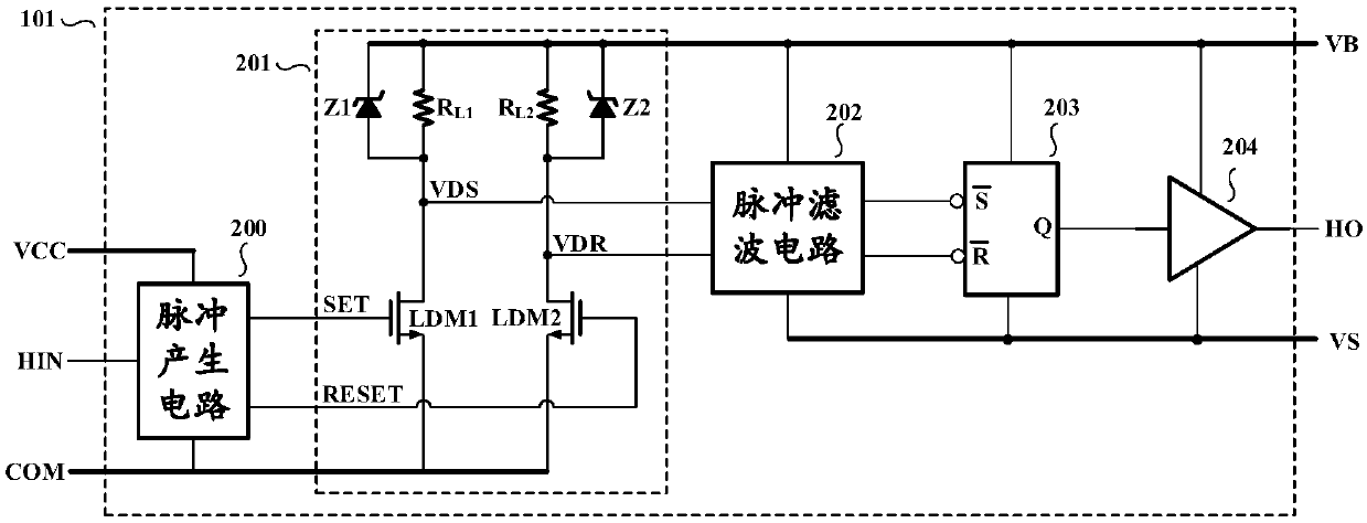
[0035] The high voltage side gate drive circuit of the present invention and Figure 2a The structures shown are the same, including a narrow pulse generation circuit 200, a high-voltage level shift circuit 201, a pulse filter circuit 202, an RS flip-flop 203 and a gate drive circuit 204, but the pulse filter circuit therein is completely identical to the pulse filter circuit 202 of the prior art Different, and the narrow pulse generation circuit, high-voltage level shift circuit, RS flip-flop and gate drive circuit also adopt a better implementation circuit to cooperate with the pulse filter circuit.

[0036] Such as Figure 4 As shown, the pulse filter circuit 202c used in the present invention includes two signal paths, the first path includes the first buffer circuit 400, the first inverter unit 402 and the first shaping circuit 404, and the second path includes the second buffer circuit 401, the second inverter unit 403 and the second shaping circuit 405, the input of th...


PUM


Abstract

The invention discloses a high-voltage side grid driving circuit for a half-bridge structure. A pulse filter circuit comprises two signal paths, wherein the two paths are respectively provided with abuffer circuit, a phase inverter unit and a shaping circuit; the two phase inverter units are respectively provided with four ports, wherein first ports of the two phase inverter units are input ends,second ports of the two phase inverter units are output ends, third ports of the two phase inverter units are fixed potential ends, and fourth ports of the two phase inverter units are floating potential ends; if an absolute value of a voltage difference between the first ports and the fourth ports is higher than threshold voltage VTH of the inverter unit, electric signals of the fourth ports canbe transmitted to the second ports through the first inverter unit or the second inverter unit; and if the absolute value of the voltage difference between the first ports and the fourth ports is nothigher than the threshold voltage VTH of the inverter unit, the electric signals of the fourth ports cannot be transmitted to the second ports through the first phase inverter unit or the second phase inverter unit.

Description

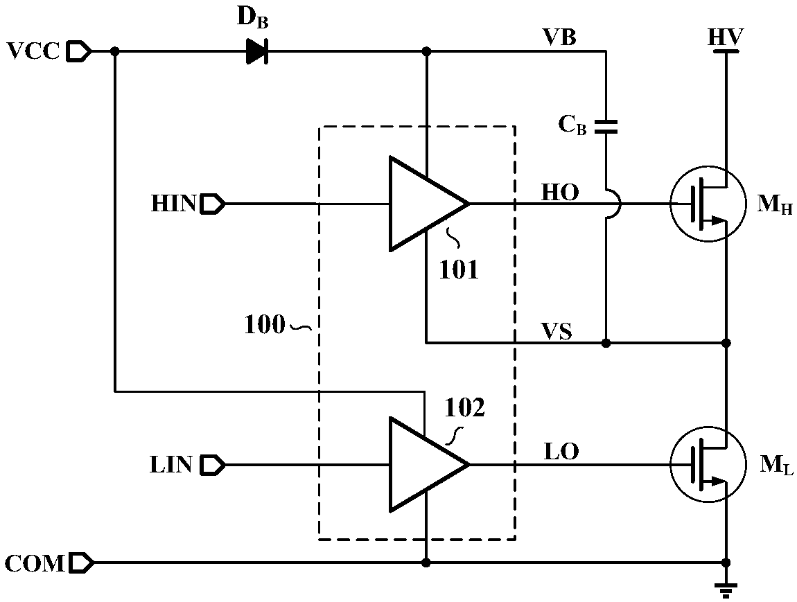
technical field [0001] The invention relates to high-voltage driving technology, in particular to a high-voltage floating gate driving circuit with high anti-noise capability and used in a half-bridge structure, which belongs to the technical field of integrated circuits. Background technique [0002] The high-voltage side gate drive circuit is an integrated circuit that controls high-voltage power switching devices to turn on and off with low-voltage signals. Because it can effectively control bridge-connected power switching devices, it is widely used in motor drives and resonant power supplies. . [0003] The high-side gate drive circuit is often used to drive the high-side switching devices in the half-bridge structure, while the low-side switching devices in the half-bridge structure are driven by the low-side gate drive circuit. Its basic topology is as figure 1 Shown, M H , M L The high-side power switching device and the low-side power switching device of the hal...

Claims


Application Information

Patent Timeline
Patent Type & Authority Applications(China)
IPC IPC(8): H03K17/687
CPCH03K17/687H03K2217/0054H03K2217/0063
Inventor 祝靖张允武陆扬扬孙伟锋陆生礼时龙兴
Owner SOUTHEAST UNIV
Learn More