
A controllable cooling device for electric welding machine

A cooling device, controllable technology, applied in the direction of auxiliary devices, welding equipment, auxiliary welding equipment, etc., can solve the problems of temperature rise, unfavorable carrying, waste of welding machine power, etc., to improve the cooling speed and cooling speed Controllable, effect of increasing cooling rate

Active Publication Date: 2019-07-09
ANHUI POLYTECHNIC UNIV
View PDF6 Cites 0 Cited by
  • Summary
  • Abstract
  • Description
  • Claims
  • Application Information

AI Technical Summary

Problems solved by technology

[0003] (1) Most of the cooling devices of electric welding machines currently in use use oil-immersed self-cooling. This method is more suitable for electric welding machines equipped with small and medium-sized transformers. The surface of the oil tank is sufficient for cooling, but for relatively high power For high-end electric welding machines, the oil-immersed self-cooling method is not enough to cool down, especially when the electric welding machine is used continuously for a long time, the oil in the oil tank is not enough to dissipate heat, causing the temperature of the electric welding machine to be too high;
[0004] (2) The cooling speed of the cooling device of the electric welding machine currently in use is fixed and cannot be adjusted according to the actual temperature in the electric welding machine. When the electric welding machine is used for a long time or in a high temperature environment In this case, the cooling speed of the electric welding machine may not keep up with the actual demand. When the electric welding machine only works intermittently for a short time, or is used in a low temperature environment, the cooling and cooling speed of the electric welding machine may be more than sufficient, thus wasting the used time of the electric welding machine. The power consumed by cooling, and the excess coolant will increase the weight of the welding machine, which is not conducive to carrying;
[0005] (3) When receiving abnormal voltage or operating errors by the operator, the temperature inside the welding machine may suddenly rise rapidly. If there is no emergency cooling device, the internal transformer may be burned

Method used


Image

  • A controllable cooling device for electric welding machine
  • A controllable cooling device for electric welding machine
  • A controllable cooling device for electric welding machine

Examples


Embodiment

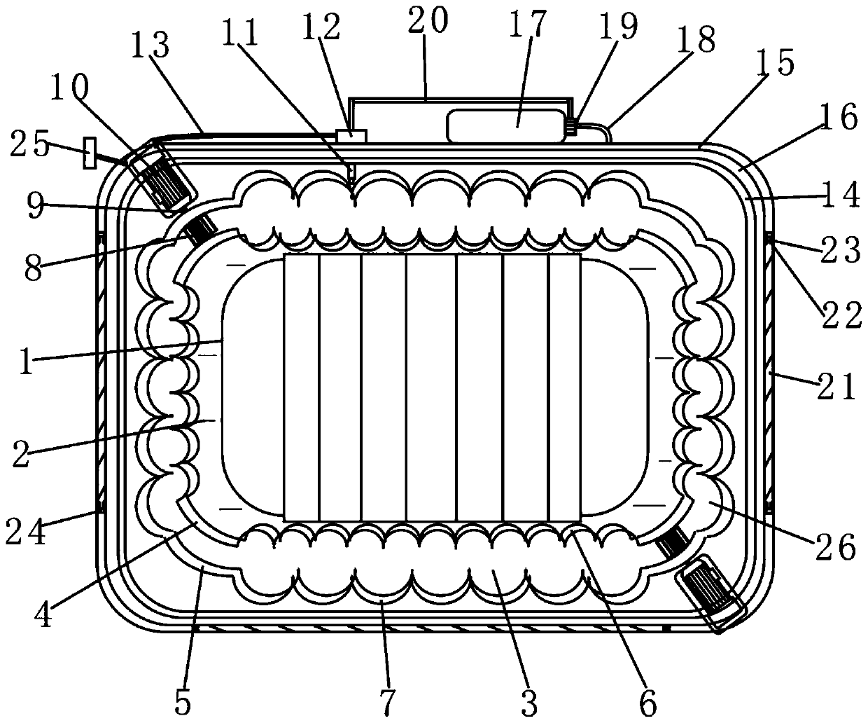
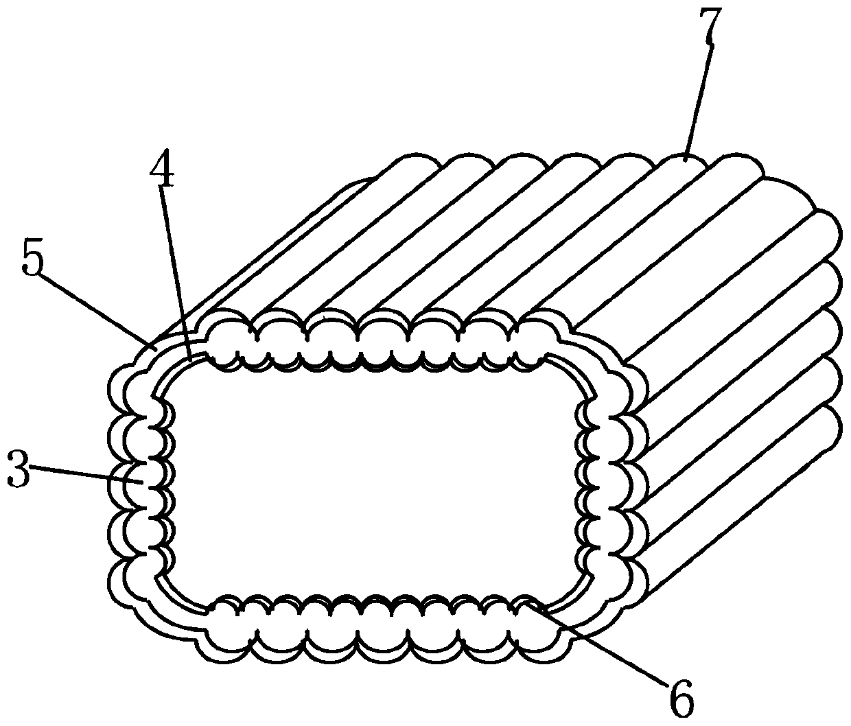
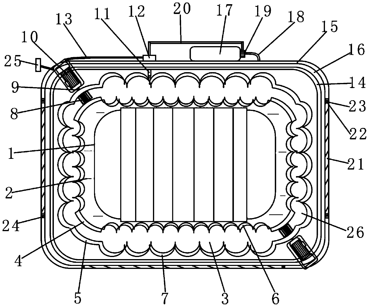
[0024] Such as figure 1 with figure 2 As shown, the present invention provides a controllable cooling device for an electric welding machine, including a transformer 1, an oil immersion liquid 2 is arranged around the outer surface of the transformer 1, and a circulating cooling chamber 3 is arranged outside the oil immersion liquid 2 , the circulating cooling chamber 3 includes an inner wall 4 and an outer wall 5, the circulating cooling chamber 3 is provided with an oil-based coolant 26, the inner wall 4 is provided with a small protrusion 6, and the outer surface of the outer wall 5 is provided with a large Protrusions 7, the cross-sections of the small protrusions 6 and the large protrusions 7 are semicircular, and the number of small protrusions 6 is not less than 10, and the number of large protrusions 7 is not less than 6. To increase the heat dissipation area, thereby speeding up the cooling rate.

[0025] Such as figure 1 with figure 2 As shown, the circulating ...


PUM


Abstract

The invention discloses a controllable cooling device for an electric welding machine. The controllable cooling device comprises a transformer. An oil immersion solution is contained around the transformer. A circulation cooling chamber is arranged outside the oil immersion solution and comprises an inner wall and an outer wall. Small protrusions are arranged on the surface of the inner wall, andlarge protrusions are arranged on the outer surface of the outer wall. Impellers are arranged inside the circulation cooling chamber and are further connected with motors through rotating shafts. A temperature probe is arranged on the upper surface of the outer wall and is further connected with a microcomputer. The microcomputer is connected with the motors. An inner sealing cavity and an outer sealing cavity are formed in the periphery of the outer wall. A gap is reserved between the inner sealing cavity and the outer sealing cavity. A liquid nitrogen bottle is fixedly installed at the top of the outer sealing cavity. The side face and the bottom of the outer sealing cavity are provided with movable plates. Due to arrangement of the circulation cooling chamber, the temperature probe andthe microcomputer, and the cooling speed of the electric welding machine can be controlled and be adjusted automatically according to the actual temperature of the inside of the electric welding machine.

Description

technical field [0001] The invention relates to the technical field of electromechanical equipment, in particular to a controllable cooling device for an electric welding machine. Background technique [0002] The electric welding machine uses the high-temperature arc generated when the positive and negative poles are short-circuited instantly to melt the solder on the electrode and the material to be welded, so as to combine the objects to be contacted. Its structure is equivalent to a high-power transformer, using the principle of inductance , the inductance will produce a huge voltage change when it is turned on and off, so that an instantaneous high-voltage arc will be generated during a short circuit. When the welding machine is running, the heat generated by the loss of the winding and the core must be dissipated in time to avoid overheating. Insulation damage is caused, and the cooling device of the current electric welding machine has the following deficiencies: [...

Claims


Application Information

Patent Timeline
Patent Type & Authority Patents(China)
IPC IPC(8): B23K37/00
CPCB23K37/003
Inventor 苗润泽张小龙杨国太
Owner ANHUI POLYTECHNIC UNIV
Learn More