Full-automatic two-sided deburring machine

A deburring machine, fully automatic technology, applied in the direction of grinding frame, grinding feed movement, grinding drive device, etc., can solve the problem of high labor intensity of operators, lack of safety guarantee, troublesome and laborious deburring, etc. Problems, to achieve the effect of convenient control, light weight, and reduce labor intensity

Pending Publication Date: 2018-02-16
GUANGZHOU RUISU INTELLIGENT TECH CO LTD
View PDF0 Cites 7 Cited by
  • Summary
  • Abstract
  • Description
  • Claims
  • Application Information

AI Technical Summary

Problems solved by technology

In the existing deburring process, the method of manual deburring is usually used to fix the sheet metal plate, and the grinding wheel is installed on the angle grinder to go back and forth, or the angle grinder is fixed, and the sheet metal is grasped by hand. There are burrs on the back and forth of the metal plate, and when there are burrs on the front and back of the sheet metal plate, it needs to be deburred again on the other side. Deburring is laborious, costly, and inefficient. Assure

Method used


Image

  • Full-automatic two-sided deburring machine
  • Full-automatic two-sided deburring machine

Examples


Embodiment Construction

[0027] The present invention will be described in further detail below.

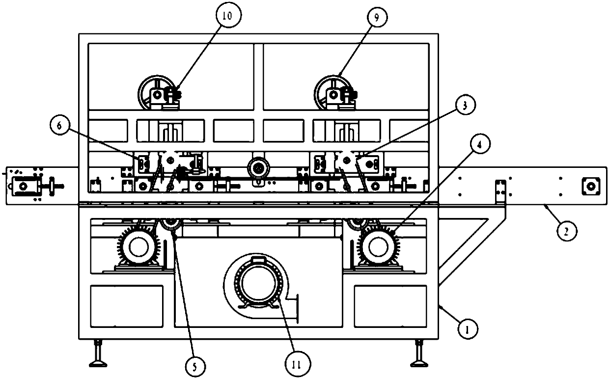
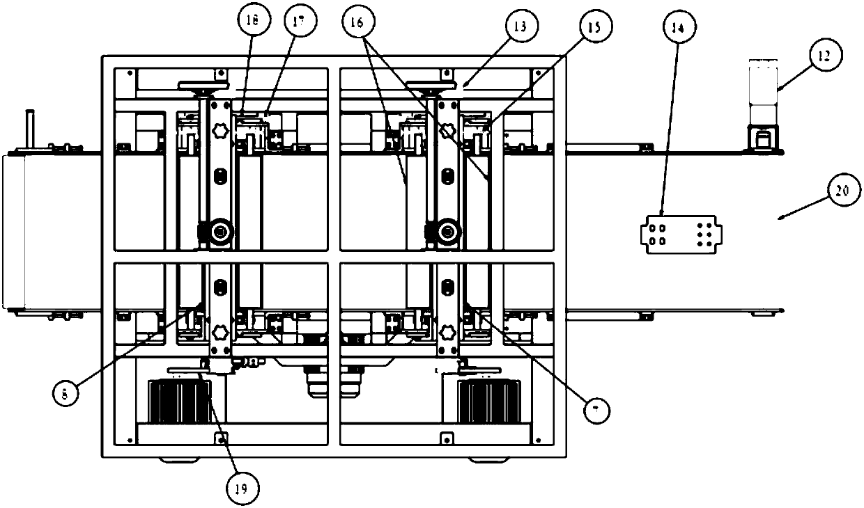
[0028] A fully automatic double-sided deburring machine includes a frame, a feeding mechanism, a forward roller brush device, a reverse roller brush device, a pressing device, a rough adjustment device, a fine adjustment device, a dust removal system, and a controller.

[0029] The feeding mechanism includes: three sections of conveyor belts, two supporting parts, a first motor, and a chain transmission mechanism. Along the conveying direction of the sheet metal plate, the first conveyor belt, the first support, the second conveyor belt, the second support, and the third conveyor belt are sequentially set on the frame, and are located on the two sides of the feeding mechanism. Between the side plates; the chain transmission mechanism connects the three conveyor belts in series, the first motor drives the three conveyor belts to rotate synchronously, and the first motor is installed on the side plate of t...


PUM

PropertyMeasurementUnit
Diameteraaaaaaaaaa
Lengthaaaaaaaaaa

Abstract

The invention relates to a full-automatic two-sided deburring machine, and belongs to machining machinery of metal plate flat workpieces. The full-automatic two-sided deburring machine comprises a machine frame, a feeding mechanism, a forward-direction rolling brush device, a reverse-direction rolling brush device and a compressing device. The feeding mechanism comprises three sections of conveying belts and two supporting pieces, the first conveying belt, the first supporting piece, the second conveying belt, and the second supporting piece and the third conveying belt are sequentially arranged on the machine frame in the conveying direction of a metal plate flat workpiece; the forward-direction rolling brush device and the reverse-direction rolling brush device each comprises a set of steel wire rolling brushes arranged up and down, the forward-direction rolling brush device is installed to correspond to the first supporting piece, and the reverse-direction rolling brush device is installed to correspond to the second supporting piece; and in one set of steel wire rolling brushes, two steel wire rolling brushes are located above and below the supporting pieces correspondingly, the metal plate flat workpiece passing through the supporting pieces is cut jointly, the compressing device comprises compressing rollers, and the compressing rollers are arranged on the front side andthe rear side of each set of steel wire rolling brushes correspondingly. According to the full-automatic two-sided deburring machine, the efficiency is improved, and the product quality is ensured.

Description

technical field [0001] The invention relates to a processing machine for sheet metal flat parts, in particular to a fully automatic double-sided deburring machine. Background technique [0002] Sheet metal flat parts generally refer to low carbon steel as the main material, which is formed by shearing or punching to form the required flat workpiece. The process of conventional sheet metal flat parts is: blanking→shearing→punching→deburring→transfer to the next process. In the existing deburring process, the method of manual deburring is usually used to fix the sheet metal plate, and the grinding wheel is installed on the angle grinder to go back and forth, or the angle grinder is fixed, and the sheet metal is grasped by hand. There are burrs on the back and forth of the metal plate, and when there are burrs on the front and back of the sheet metal plate, it needs to be deburred again on the other side. Deburring is laborious, costly, and inefficient. Assure. [0003] Ther...

Claims


Application Information

Patent Timeline
IPC IPC(8): B24B9/04B24B27/00B24B41/00B24B47/12B24B41/02B24B55/06
CPCB24B9/04B24B27/0076B24B41/005B24B41/02B24B47/12B24B55/06
Inventor 伍波耿魁伟王海军
Owner GUANGZHOU RUISU INTELLIGENT TECH CO LTD
Why Eureka
Try Eureka