Underground floater cleaning grass fisher
A floating object, photoelectric sensor technology, applied in construction, drinking water installations, water supply installations, etc., can solve the problems affecting the normal use of wells, inconvenient operation, difficult equipment, etc., and achieve the effect of saving manpower, reducing strength and weight.
- Summary
- Abstract
- Description
- Claims
- Application Information
AI Technical Summary
Problems solved by technology
Method used
Image
Examples
Embodiment 1
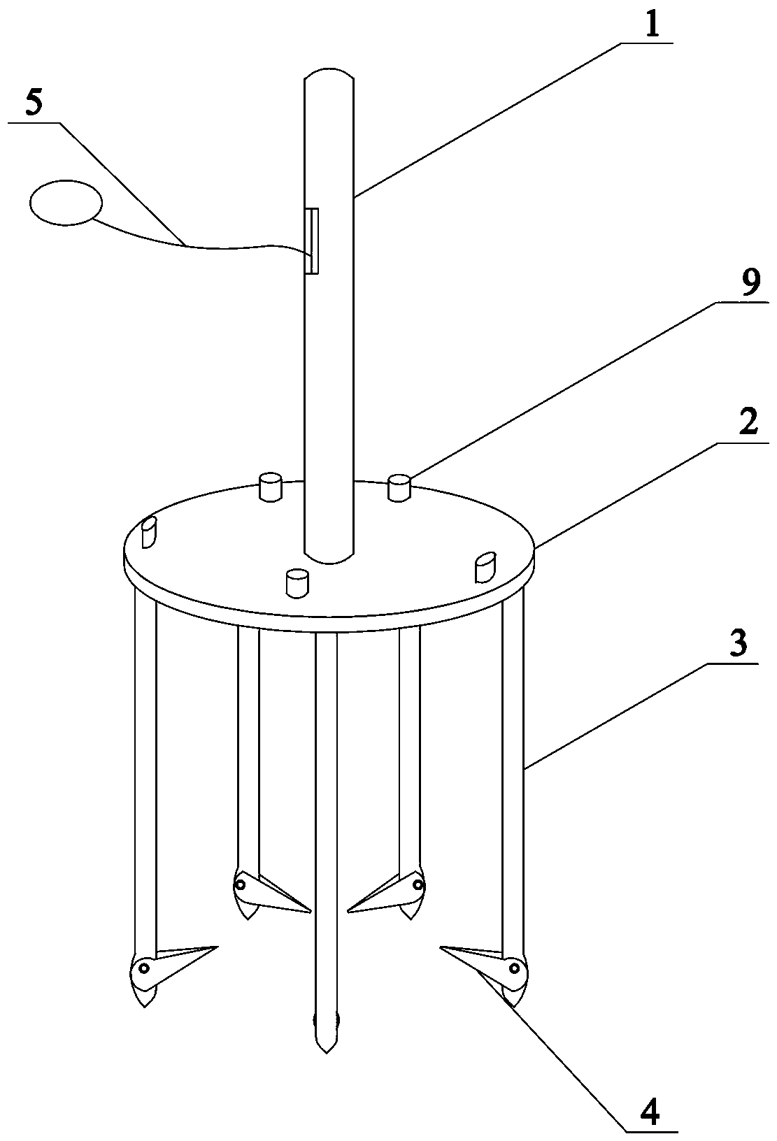
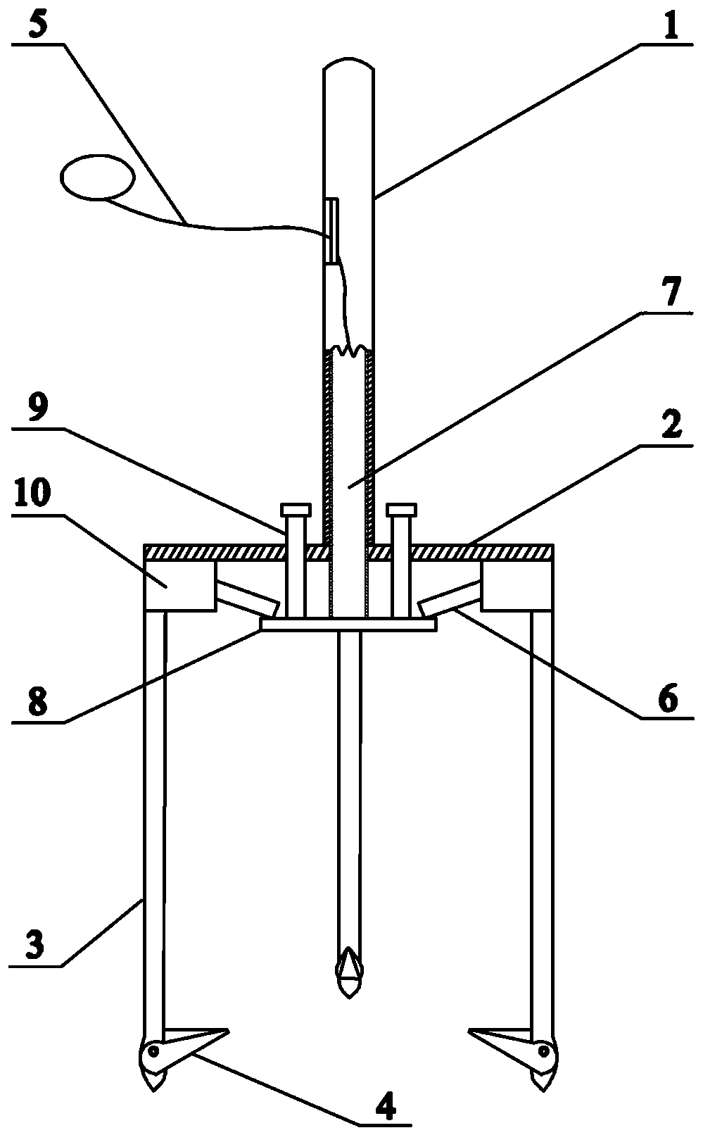
[0033] Such as Figure 1~4 As shown, a kind of downhole floating debris cleaning grass catcher includes a disc 2, a tray 8, a grass catcher rod 1, a first inner tube 7, a tray tensioning line 5 and 5 mechanical claws, and the diameter of the tray 8 is Less than the diameter of the disc 2; the grass catcher rod 1 is an inner hollow structure, the lower end of the grass catcher rod 1 is fixed at the center of the disc 2, and the center of the disc 2 is provided with a hole, so One end of the first inner tube 7 passes through the hole and enters the inside of the grass catcher rod 1 and is connected with one end of the pallet tensioning wire 5, and the other end of the first inner tube 7 is fixed on the tray 8 In the center, the other end of the pallet tensioning wire 5 protrudes from the grass catcher rod 1 .
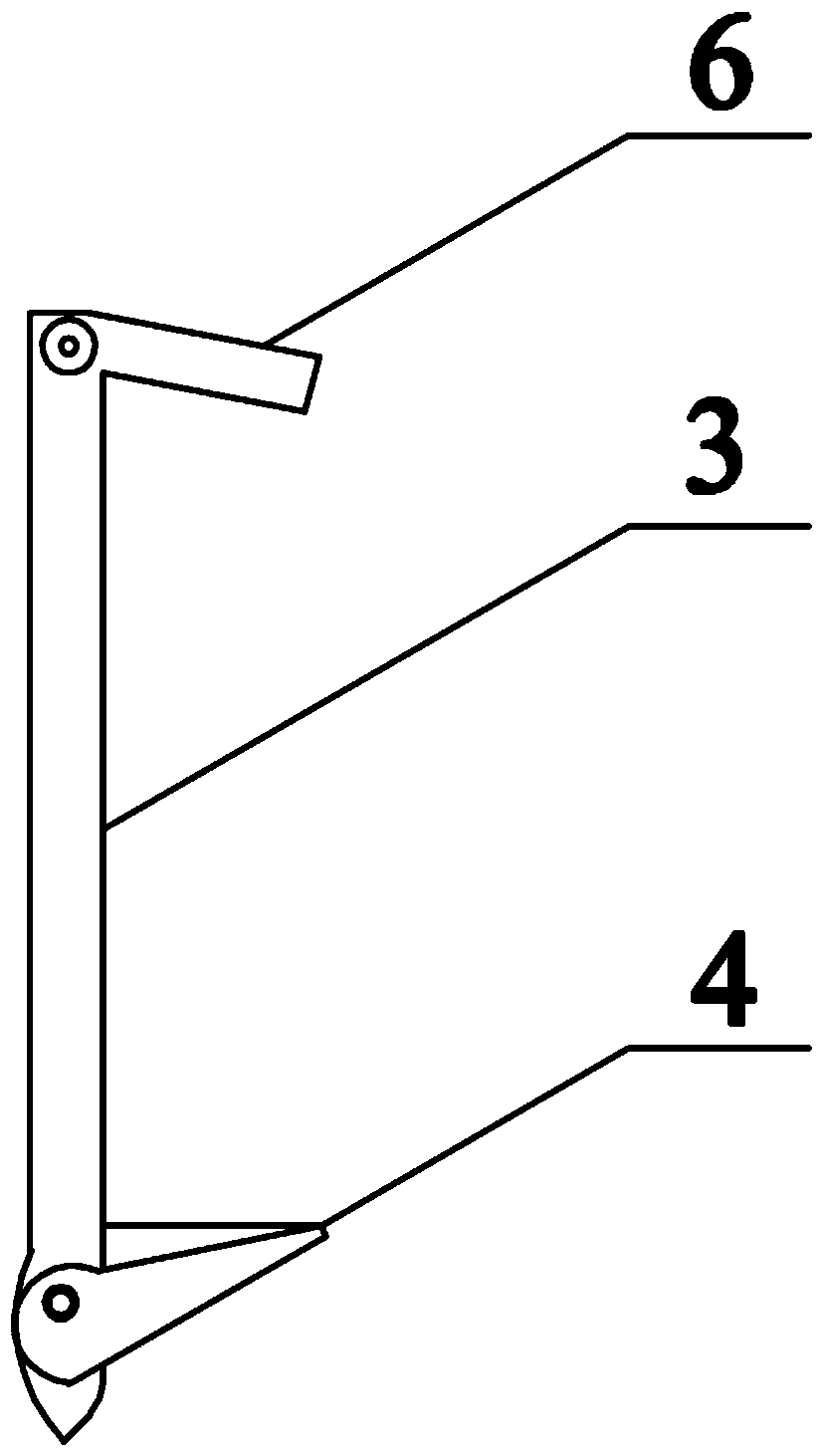
[0034] The mechanical claw includes a probing leg 3, a probing leg cross arm 6 and a probing tongue 4, the top of each probing leg 3 is evenly distributed along the circ...
Embodiment 2
[0040] The difference between this embodiment and embodiment 1 is: as Figure 7 As shown, the downhole floating debris cleaning grass catcher also includes a squeezing device, and the squeezing device includes a pressure plate 12, a pressure plate tension line 13 and a second inner pipe 11, and the pressure plate 12 is selected to have a density much higher than that of water. A solid disc such as an iron disc, the outer diameter of the second inner tube 11 is smaller than the inner diameter of the first inner tube 7, the center of the tray 8 is provided with a central hole corresponding to the second inner tube 11, the The radius of the pressure plate 12 is smaller than the radius of the disc 2; one end of the second inner tube 11 passes through the central hole and extends into the first inner tube 7 and an end of the pressure plate tension wire 13 connected, the other end of the second inner tube 11 is fixed at the center of the pressure plate 12, and the other end of the p...
Embodiment 3
[0043] The difference between this embodiment and embodiment 1 is: as Figure 5 As shown, the tray 8 is provided with a slide groove 15 corresponding to one end of each leg probe arm 6, and the extension direction of each slide groove 15 is consistent with the stroke direction of the leg probe arm 6. One end of the arm 6 falls into the corresponding sliding groove 15 and can move back and forth along the sliding groove 15 . Combined with the structure of the guide plate, the instability of the single-point limit of the guide plate is avoided, and the movement range of the detection leg is further ensured to be in a stable plane through the two-point limit.
PUM
 Abstract
Description
Claims
Application Information
 - R&D
- Intellectual Property
- Life Sciences
- Materials
- Tech Scout
- Unparalleled Data Quality
- Higher Quality Content
- 60% Fewer Hallucinations
Browse by: Latest US Patents, China's latest patents, Technical Efficacy Thesaurus, Application Domain, Technology Topic, Popular Technical Reports.
© 2025 PatSnap. All rights reserved.Legal|Privacy policy|Modern Slavery Act Transparency Statement|Sitemap|About US| Contact US: help@patsnap.com


