Mixed cooling system for unmanned helicopter engine

An unmanned helicopter and hybrid cooling technology, applied in the cooling of engines, machines/engines, engine components, etc., can solve the problem that the technical characteristics of unmanned helicopters cannot be exerted, the heat dissipation effect of air-cooled engines is not ideal, and the battery life of unmanned helicopters is shortened. Time and other issues, to achieve the effect of large adjustable temperature range, improved cooling effect, and improved large load

Pending Publication Date: 2018-02-16
SHENYANG INST OF AUTOMATION - CHINESE ACAD OF SCI
View PDF0 Cites 2 Cited by
  • Summary
  • Abstract
  • Description
  • Claims
  • Application Information

AI Technical Summary

Problems solved by technology

The best use state of the air-cooled heat dissipation method is the high-speed forward flight state of the unmanned helicopter. However, in actual aviation applications, due to mission requirements, the unmanned helicopter usually works at a low forward flight speed or hovering state. At this time, the air-cooled engine The heat dissipation effect is very unsatisfactory; the water-cooling heat dissipation method usually controls the start and stop of the water-cooling cycle according to a preset single temperature threshold, which cannot be automatically adjusted according to the temperature, resulting in waste of resources and shortening the battery life of unmanned helicopters
Especially for long-endurance unmanned helicopters with oil-driven large loads, a single air-cooled or water-cooled method cannot give full play to the technical characteristics of large loads and long-endurance unmanned helicopters

Method used


Image

  • Mixed cooling system for unmanned helicopter engine
  • Mixed cooling system for unmanned helicopter engine
  • Mixed cooling system for unmanned helicopter engine

Examples


Embodiment Construction

[0024] In order to make the object, technical solution and advantages of the present invention clearer, the present invention will be described in detail below in conjunction with the accompanying drawings and specific embodiments.

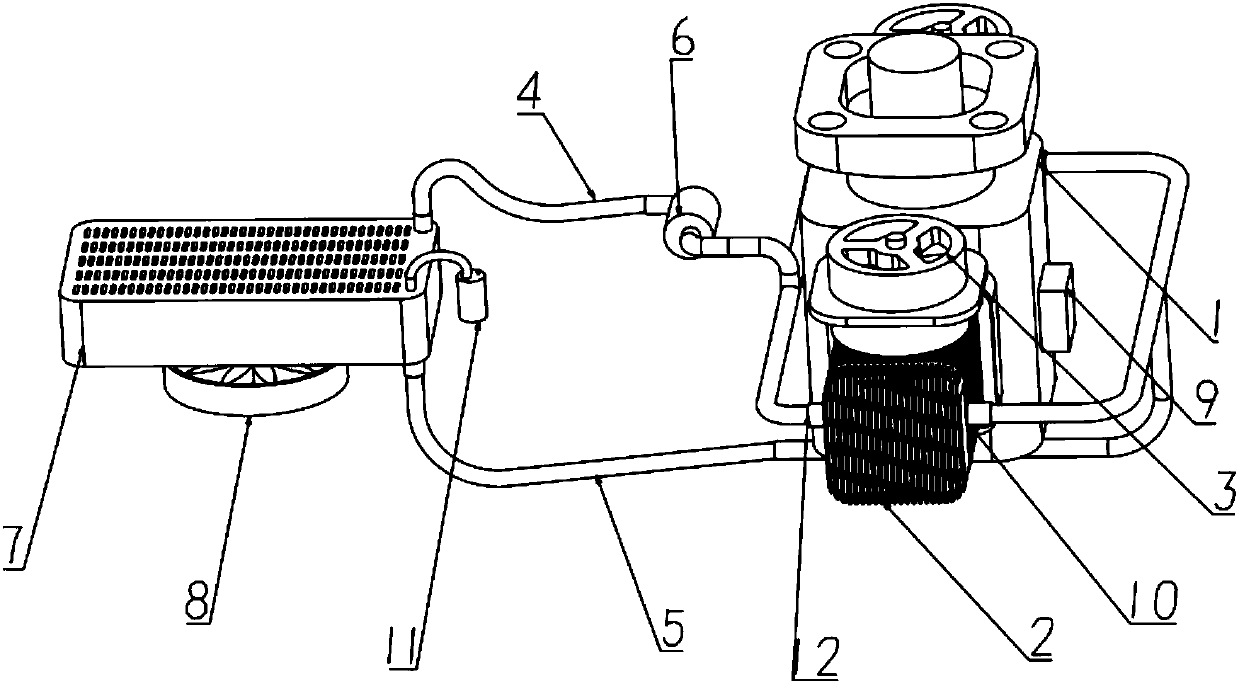
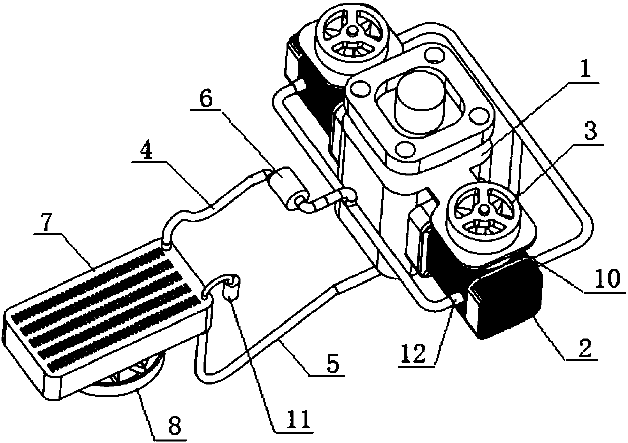
[0025] Such as Figure 1-2 As shown, a kind of unmanned helicopter engine hybrid cooling system provided by the present invention comprises water-cooled cylinder jacket 2, water-cooled cylinder jacket water outlet pipe 4, water-cooled cylinder jacket water inlet pipe 5, water pump 6, cooling radiator 7 and temperature control system, wherein The water-cooled cylinder liner 2 is set on the engine cylinder head 1. The water-cooled cylinder liner 2 and the cooling radiator 7 are connected to form a circulation loop through the water-cooled cylinder liner outlet pipe 4 and the water-cooled cylinder liner inlet pipe 5. The water pump 6 is installed on the water-cooled cylinder liner. On the water outlet pipe 4, the temperature control system is used to...


PUM


Abstract

The invention relates to an cooling system for an engine, in particular to a mixed cooling system for an unmanned helicopter engine. The mixed cooling system comprises a water cooling cylinder sleeve,a water cooling cylinder sleeve water outlet pipe, a water cooling cylinder sleeve water inlet pipe, a water pump, a cooling radiator and a temperature control system; the water cooling cylinder sleeve is arranged on an engine cylinder head in a sleeving mode, and the water cooling cylinder sleeve and the cooling radiator are connected into a circulation loop through the water cooling cylinder sleeve water outlet pipe and the water cooling cylinder sleeve water inlet pipe; and the water pump is arranged on the water cooling cylinder sleeve water outlet pipe, and the temperature control systemis used for monitoring the temperature in the water cooling cylinder sleeve and controlling starting of the water pump according to the monitoring value; a first cooling fan is arranged above the water cooling cylinder sleeve, a second cooling fan is arranged on one side of the cooling radiator, and the first cooling fan and the second cooling fan are connected with a temperature controller. Themixed cooling system has the advantages of being high in cooling efficiency, wide in adjustable temperature range, automatic in height control and the like; and in addition, the temperature controllercan automatically select a corresponding cooling mode according to the water temperature range so that resource waste can be avoided.

Description

technical field [0001] The invention relates to an engine cooling system, in particular to an unmanned helicopter engine hybrid cooling system. Background technique [0002] Oil-powered large-load long-endurance unmanned helicopters often use aviation piston engines as power devices. This type of engine can provide maximum power output while ensuring optimal weight. Most of the existing aviation piston engines are air-cooled or water-cooled. Cool the engine. The best use state of the air-cooled heat dissipation method is the high-speed forward flight state of the unmanned helicopter. However, in actual aviation applications, due to mission requirements, the unmanned helicopter usually works at a low forward flight speed or hovering state. At this time, the air-cooled engine The heat dissipation effect is very unsatisfactory; the water-cooling heat dissipation method usually controls the start and stop of the water-cooling cycle according to a preset single temperature thres...

Claims


Application Information

Patent Timeline
IPC IPC(8): F01P9/04F01P11/16F01P7/04F01P7/08F01P7/16F02F1/00
CPCF01P7/026F01P7/04F01P7/048F01P7/08F01P7/16F01P7/162F01P7/165F01P9/04F01P11/16F02F1/004F01P2050/20
Inventor 何玉庆杨丽英李思梁于海涛
Owner SHENYANG INST OF AUTOMATION - CHINESE ACAD OF SCI
Why Eureka
Try Eureka