
Dehumidifying fan of drying machine

A technology of dryer and fan, applied in the field of machinery, can solve the problems of impeller collision, need of space, fan damage, etc., and achieve the effect of avoiding strong collision and prolonging life.

Inactive Publication Date: 2018-02-16
浙江四合风机有限公司
View PDF0 Cites 0 Cited by
  • Summary
  • Abstract
  • Description
  • Claims
  • Application Information

AI Technical Summary

Problems solved by technology

Because the drying method of sunlight exposure requires a site, the operation is inconvenient and is greatly affected by weather factors, the temperature is not controlled
Therefore, it is a better choice to use a dehumidification fan to dry the material. However, the existing dehumidification fans are not equipped with a device for blocking metal particle impurities at the air inlet, resulting in the metal particle impurities being sucked by the dehumidification fan. It is easy to collide with the impeller and cause damage to the fan

Method used


Image

  • Dehumidifying fan of drying machine
  • Dehumidifying fan of drying machine

Examples


Embodiment Construction

[0012] The following are specific embodiments of the present invention and in conjunction with the accompanying drawings, further describe the technical solution of the present invention, but the present invention is not limited to these embodiments.

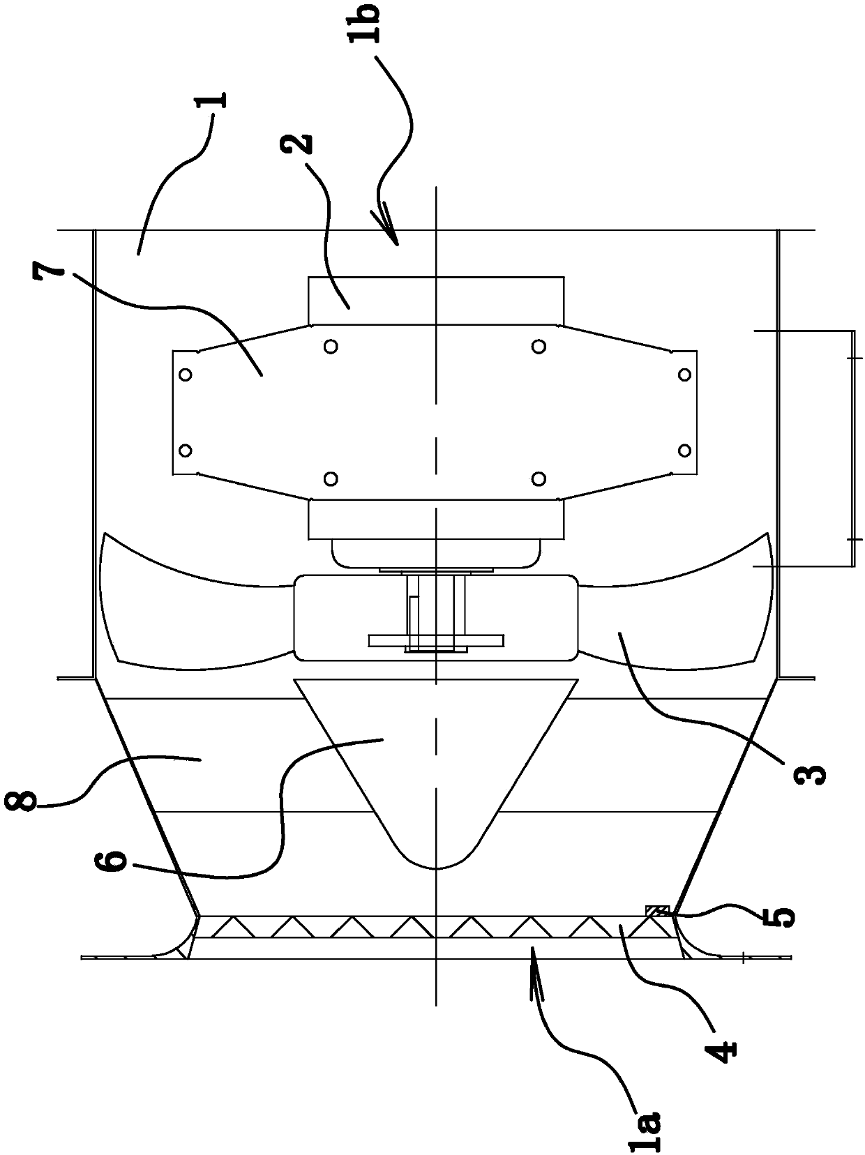
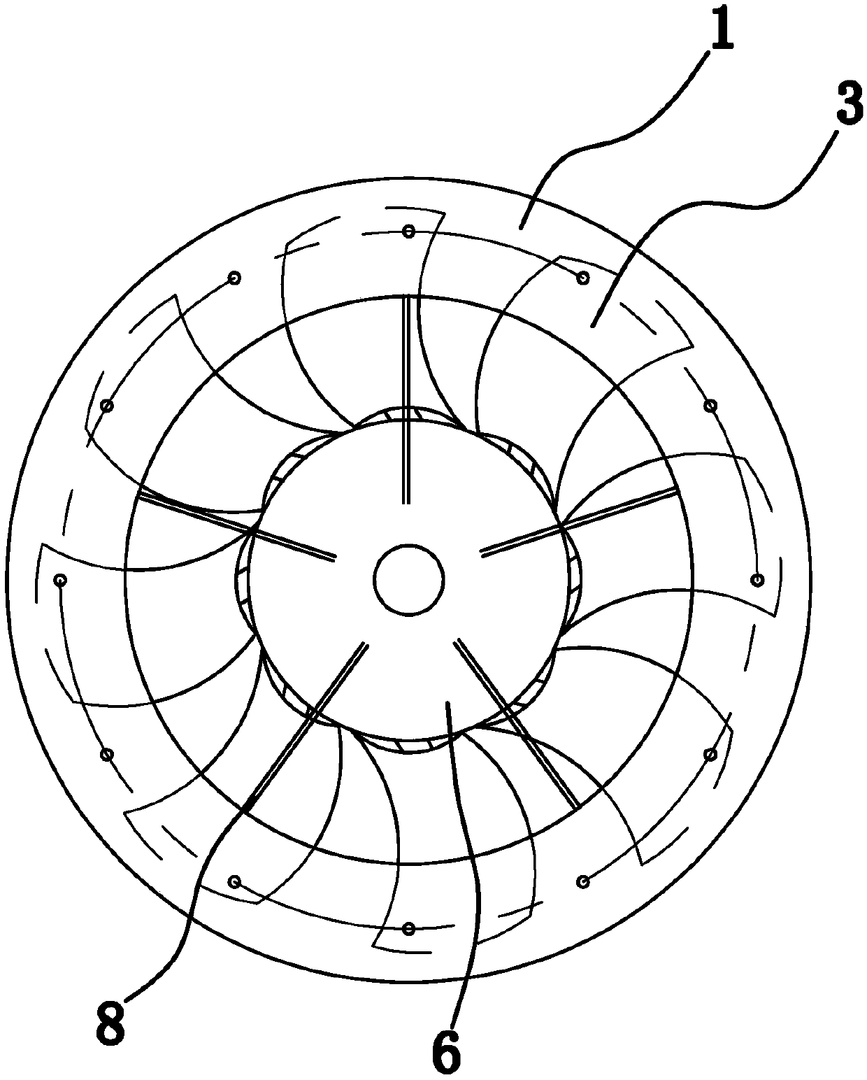
[0013] Such as figure 1 with figure 2 As shown, the dehumidification blower of the dryer is composed of a barrel 1, a motor 2, an impeller 3, a filter screen 4, a magnetic block 5, and a diversion cap 6. Wherein, the filter screen 4 is made of magnetic material, and the magnetic material can be iron or an alloy containing iron.

[0014] Specifically, the barrel 1 is cylindrical, and its two ends are respectively an air inlet 1a and an air outlet 1b. Both the motor 2 and the impeller 3 are located in the machine barrel 1, wherein the motor 2 is fixedly connected to the machine barrel 1 through the support 7, the impeller 3 is located between the motor 2 and the air inlet 1a, and the impeller 3 is connected to the main shaft of...


PUM


Abstract

The invention provides a dehumidification blower of a dryer, which belongs to the technical field of machinery. It solves the problem of short service life of the existing fans. The dehumidification blower of this dryer includes a machine barrel with an air inlet and an air outlet. A motor is fixed inside the barrel, and an impeller is fixed on the motor shaft. The impeller is in the barrel and is located between the air inlet and the motor. There is a filter screen, and the inner wall of the cylinder at the air inlet is the first cone, and the diameter of the first cone gradually decreases from the air inlet to the direction of the impeller. The first and the second conical surfaces are closely attached to form a seal, and a magnetic block is fixedly connected to the filter, and the magnetic block is located between the filter screen and the impeller, and the filter screen is made of magnetic material. The dehumidification blower of the dryer has the advantage of long life.

Description

technical field [0001] The invention belongs to the technical field of machinery, and relates to a dryer, in particular to a moisture exhaust fan of the dryer. Background technique [0002] At present, in the manufacturing process of some materials, in order to reduce the moisture content of the materials and ensure the safety and good effect of material storage, the materials must be dried. Many materials cannot be baked directly with an open flame, and there are strict requirements on the temperature of the drying room, and the materials to be baked must be isolated from the heat source. There are two commonly used drying methods for materials, natural drying by sunlight, or drying with a dehumidifier. Because the drying method of sunlight requires a site, the operation is inconvenient, and it is greatly affected by weather factors, and the temperature is not controlled. Therefore, it is a better choice to use a dehumidification fan to dry the material. However, the exis...

Claims


Application Information

Patent Timeline
IPC IPC(8): F04D25/08F04D29/70F04D29/00
CPCF04D25/08F04D29/002F04D29/703
Inventor 吴文彬
Owner 浙江四合风机有限公司
Learn More