Check patentability & draft patents in minutes with Patsnap Eureka AI!

A cooling tray device and wafer etching equipment

A tray and chip loading technology, applied in the field of microelectronics, can solve the problems of etching process failure, affecting the performance of plasma processing equipment, small gas flow, etc., and achieve the effect of significant heat dissipation effect.

Active Publication Date: 2019-11-08
DYNAX SEMICON
View PDF4 Cites 0 Cited by
  • Summary
  • Abstract
  • Description
  • Claims
  • Application Information

AI Technical Summary

Problems solved by technology

[0003] At present, the general-purpose tray usually has a plurality of air intake holes on the tray, and the following problems inevitably exist in practical applications, namely: since the middle air intake holes are scattered at the loading position, the heat exchange gas diffuses to the surroundings through the air intake holes. The diffusion radius tends to evenly reach all areas of the loading position. Due to the small gas flow rate in the hole, the temperature of the etching area at the loading position rises rapidly during the high-power etching process, and the surface temperature of the wafer far exceeds the temperature required by the process. It leads to the failure of the etching process and affects the performance of the plasma processing equipment. The temperature difference between the regions leads to poor temperature uniformity at the loading position, which affects the process uniformity of the plasma processing equipment.

Method used


Image

  • A cooling tray device and wafer etching equipment
  • A cooling tray device and wafer etching equipment
  • A cooling tray device and wafer etching equipment

Examples


no. 1 example

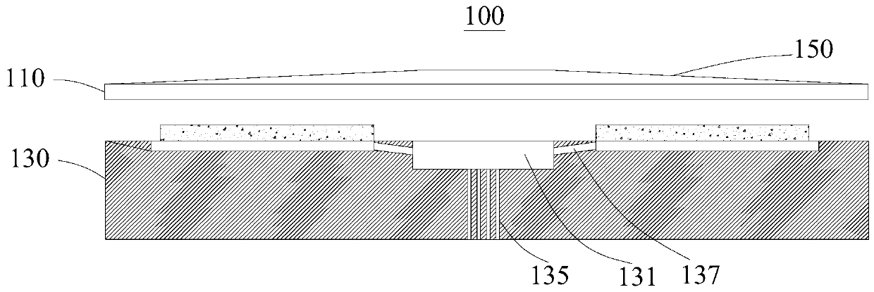
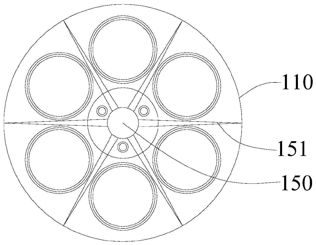
[0034] see in conjunction Figure 1 to Figure 3 , this embodiment provides a heat dissipation tray device 100, which is installed on a stage (not shown) and used for loading wafers. The heat dissipation tray device 100 includes a cover plate 110, a tray 130 and a reinforcement structure 150. The tray 130 is used for The cover plate 110 is detachably mounted on the tray 130 and is detachably connected to the object platform. The reinforcing structure 150 is fixedly connected to the cover plate 110 for strengthening the cover plate 110 .

[0035] In this embodiment, the cover plate 110 is made of alumina ceramics, and the content of alumina in the alumina ceramics is 99%. The alumina ceramics with this proportion have a larger coefficient of thermal expansion and stronger heat bearing capacity.

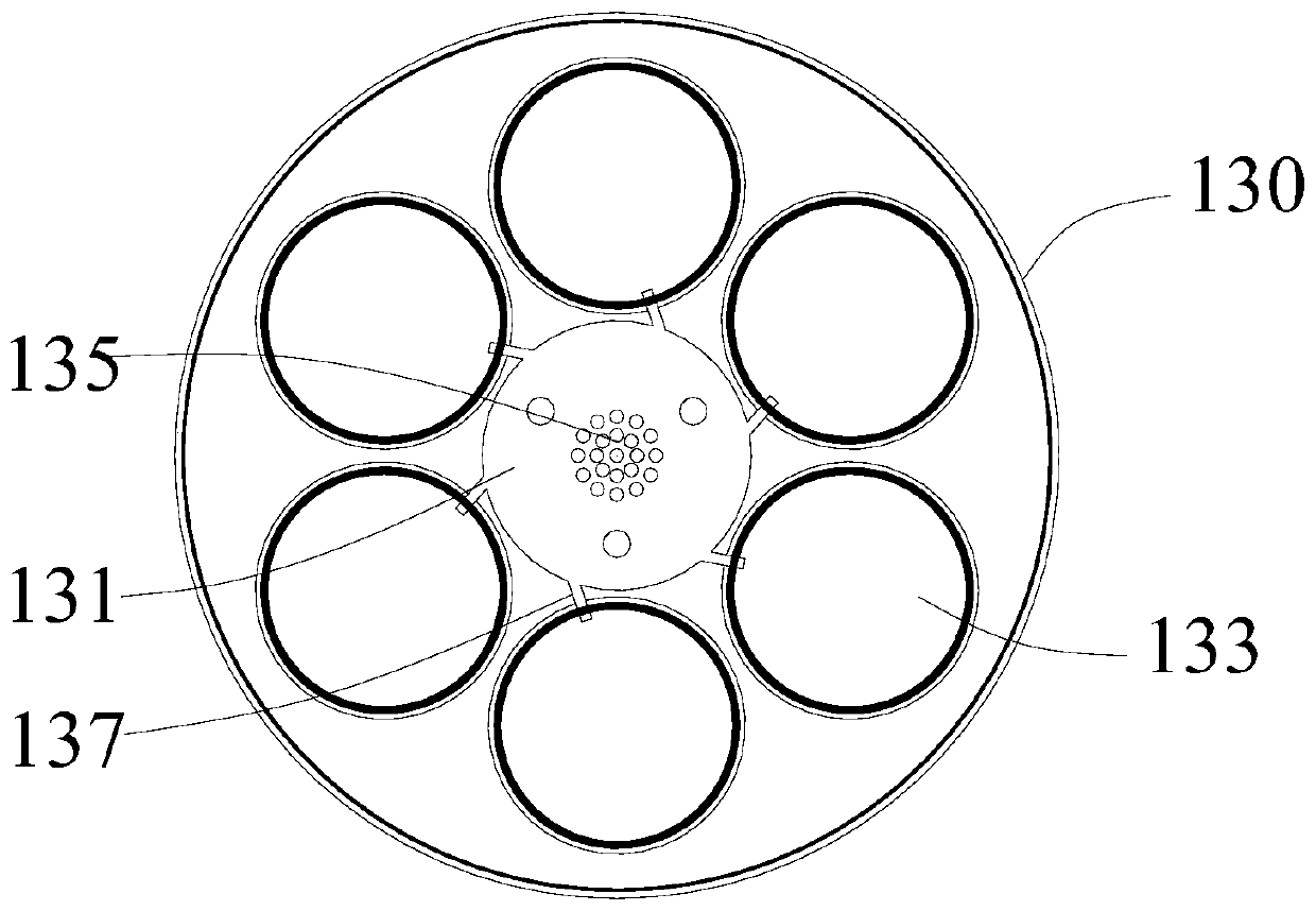
[0036] The tray 130 is provided with a ventilation groove 131 and at least one chip loading groove 133, the chip loading groove 133 is used to accommodate the wafer, and the bottom of ...

no. 2 example

[0055] see Figure 5 , this embodiment provides a wafer etching device 200, including the device housing 210, the stage 230 and the cooling tray device 100, wherein the basic structure and principle of the cooling tray device 100 and the technical effects produced are the same as those of the first embodiment Similarly, for brief description, for parts not mentioned in this embodiment, reference may be made to the corresponding content in the first embodiment.

[0056] The heat dissipation tray device 100 includes a cover plate 110 and a tray 130 , and the cover plate 110 is detachably covered on the tray 130 . The tray 130 is provided with a ventilation groove 131 and at least one chip loading groove 133, the chip loading groove 133 is used to accommodate the wafer, and the bottom of the ventilation groove 131 has a cooling gas through hole 135 for passing in cooling gas, The bottom of the chip loading groove 133 has an air intake channel 137 , and the ventilation groove 131...


PUM


Abstract

The invention provides a heat dissipation tray apparatus and wafer etching equipment, and relates to the technical field of micro-electronics. The wafer etching equipment comprises an equipment shell,an objective table and the heat dissipation tray apparatus; the heat dissipation tray apparatus comprises a cover plate and a tray; the cover plate detachably covers the tray; a ventilating groove and at least one wafer-loading groove are formed in the tray; each wafer-loading groove is used for accommodating the corresponding wafer; cooling gas through holes for pumping cooling gas are formed inthe bottom of the ventilating groove; an air inlet channel is formed in the bottom of each wafer-loading groove; the ventilating groove is connected with the air inlet channels to allow the cooling gas to enter the wafer-loading grooves; the equipment shell covers the objective table; the tray is detachably connected to the objective table; a cooling gas channel is formed in the objective table;the cooling gas through holes are connected with the cooling gas channel. Compared with the prior art, the heat dissipation tray apparatus provided by the invention allows the cooling gas to uniformlyenter the wafer-loading grooves to cool the wafer-loading grooves, so that a very remarkable heat dissipation effect is achieved.

Description

technical field [0001] The invention relates to the technical field of microelectronics, in particular to a heat dissipation tray device and wafer etching equipment. Background technique [0002] Plasma processing equipment is a common equipment for processing semiconductor devices. During the process of etching, sputtering and chemical vapor deposition, etc., in order to improve the production efficiency of plasma processing equipment and reduce production costs, generally larger size The tray is used to carry multiple wafers and transport them to the reaction injection chamber at the same time, so as to realize the simultaneous processing of multiple wafers. [0003] At present, the general-purpose tray usually has a plurality of air intake holes on the tray, and the following problems inevitably exist in practical applications, namely: since the middle air intake holes are scattered at the loading position, the heat exchange gas diffuses to the surroundings through the ai...

Claims


Application Information

Patent Timeline
Patent Type & Authority Patents(China)
IPC IPC(8): H01L21/67H01L21/673H01L21/687
CPCH01L21/67011H01L21/67063H01L21/673H01L21/68714
Inventor 胡启琼
Owner DYNAX SEMICON
Features
  • R&D
  • Intellectual Property
  • Life Sciences
  • Materials
  • Tech Scout
  • Unparalleled Data Quality
  • Higher Quality Content
  • 60% Fewer Hallucinations
Learn More