Direct-current solid-state relay

A solid-state relay and DC input technology, applied in electrical components, electronic switches, pulse technology, etc., can solve the problems of inapplicability of solid-state relays, unfavorable power system energy saving, large volume, etc., and achieve obvious energy-saving effect, small volume, and simple circuit Effect

Active Publication Date: 2018-02-16
MORNSUN GUANGZHOU SCI & TECH
View PDF6 Cites 3 Cited by
  • Summary
  • Abstract
  • Description
  • Claims
  • Application Information

AI Technical Summary

Problems solved by technology

[0006] (1) Part of the energy stored in the line at the load end is consumed by the heat generated by the resistor R, and the other part is stored and absorbed by the capacitor C. When the fault is eliminated, the switch S is turned on, and the capacitor C will discharge. The absorbing circuit 4 is a lossy absorption, not Conducive to the energy saving of the power system;
[0007] (2) When the energy stored in the load-side line is large, the RC is required to be large in size and high in cost, which is not suitable for medium and high-power solid-state relays
[0010] The above-mentioned high-voltage and high-current situations all require the application of high-power DC solid-state relays. There is no technical solution with small size, low cost and energy saving in the prior art.

Method used


Image

  • Direct-current solid-state relay
  • Direct-current solid-state relay
  • Direct-current solid-state relay

Examples


no. 1 example

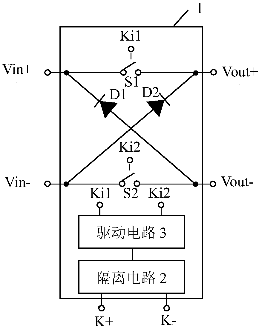
[0053] image 3 Shown is the principle diagram of the first embodiment of the present invention. This embodiment includes six terminals, namely DC input positive terminal Vin+, DC input negative terminal Vin-, DC output positive terminal Vout+, DC output negative terminal Vout-, control terminal positive Terminal K+ and control terminal negative terminal K-; also includes: shell 1, isolation circuit 2, drive circuit 3, first switch S1, second switch S2, first diode D1 and second diode D2; first The switch S1 is connected between the DC input positive terminal Vin+ and the DC output positive terminal Vout+, the second switch S2 is connected between the DC input negative terminal Vin- and the DC output negative terminal Vout-, and the anode of the first diode D1 is connected to the DC Output negative terminal Vout-, the cathode of the first diode D1 is connected to the positive DC input terminal Vin+, the anode of the second diode D2 is connected to the negative DC input termina...

no. 2 example

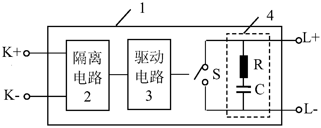
[0069] Figure 5 It is the principle diagram of the second embodiment of the present invention, compared figure 1 The difference is that a series circuit composed of a resistor R1 and a capacitor C1 is connected in parallel at both ends of the switch S1, and a series circuit composed of a resistor R2 and a capacitor C2 is connected in parallel at both ends of the switch S2.

[0070] It should be noted that the positions of the resistor R1 and the capacitor C1 can be exchanged, and the positions of the resistor R2 and the capacitor C2 can also be exchanged, which is equivalent to an RC series device after exchanging positions, which is common knowledge for those skilled in the art .

[0071] From t1 to t2, the current in switch S1 is shunted through the RC buffer branch composed of resistor R1 and capacitor C1, which reduces the burden on switch S1 and suppresses du / dt and overvoltage. When diode D2 is turned on at t2 , the current in the RC snubber branch is quickly transfer...

no. 3 example

[0075] Figure 6 It is the principle diagram of the third embodiment of the present invention, compared Figure 5 The difference is that a capacitor C3 is connected in parallel at both ends of the diode D1, and a capacitor C4 is connected in parallel at both ends of the diode D2.

[0076] From t1 to t2, a charging current will be formed in capacitor C3 and capacitor C4, which accelerates the absorption of current in switches S1 and S2, so that the current in switches S1 and S2 decreases and the peak voltage decreases, further suppressing du / dt and Overvoltage, so that the reverse voltage of diodes D1 and D2 will not be too large and be damaged by breakdown; when diodes D2 and D1 are turned on at t2 to form a absorption loop, capacitors C3 and capacitors C4 begin to discharge.

[0077] In this embodiment, there are certain problems in the switch-on process: when the switch S1 turns from off to on, the capacitor C4 is directly connected to the positive DC input and the negative...


PUM


Abstract

The invention discloses a solid-state relay. The solid-state relay comprises a direct current input positive terminal, a direct current input negative terminal, a direct current output positive terminal, a direct current output negative terminal, a control end positive terminal, a control end negative terminal, an isolating circuit, a driving circuit, a first switch, a second switch, a first diodeand a second diode. A dual-switch and dual-freewheel-diode cross connection way is adopted, energy stored in a load end line cannot be changed suddenly, and a novel path is found for continuous flowof current through freewheel diodes. The energy stored in the load-end line is fed back to a direct-current power grid through the path, thereby realizing lossless energy recovery of energy. Moreover,the product is small in size, low in cost and suitable for high-power occasions.

Description

technical field [0001] The invention relates to a solid state relay, in particular to a DC solid state relay. Background technique [0002] The schematic diagram of the existing solid state relay is as follows: figure 1 As shown, it consists of control terminal positive terminal K+ and control terminal negative terminal K-, load terminal positive terminal L+ and load negative terminal L-, shell 1, internal isolation circuit 2, drive circuit 3 and switch S. The isolation circuit 2 is used to isolate the low-voltage control terminal and the high-voltage load terminal, and the drive circuit 3 is used to amplify the weak control signal input from the low-voltage control terminal and provide it to the switch S to drive the high-current load at the load terminal. [0003] When the existing solid-state relay is disconnected, a very large peak voltage will be generated at both ends of the switch S. Therefore, it is necessary to connect an absorbing circuit 4 in parallel at both end...

Claims


Application Information

Patent Timeline
Patent Type & Authority Applications(China)
IPC IPC(8): H03K17/081H03K17/567H03K17/687H03K17/72
Inventor 尹向阳王保均陶小丽
Owner MORNSUN GUANGZHOU SCI & TECH
Why Eureka
Try Eureka