
Lifting adjustable greenhouse subsoiler

A technology of subsoiler and regulating chamber, which is applied in fields such as tillage machinery, agricultural machinery and implements, and application, and can solve problems such as soil capillary damage, large machine size, and reduction of earthworms.

Inactive Publication Date: 2018-02-23
HEBEI AGRICULTURAL UNIV.
View PDF12 Cites 0 Cited by
  • Summary
  • Abstract
  • Description
  • Claims
  • Application Information

AI Technical Summary

Problems solved by technology

[0002] With the rapid development of facility agriculture in my country, the planting area has ranked first in the world, but the degree of mechanization is low, and the subsoiling operation as an important agronomy has not been solved. As we all know, the continuous operation of small and medium-sized agricultural machinery in the greenhouse has caused The large reduction of earthworms and other organisms, the destruction of soil capillaries, the destruction of soil nutrient transport capacity, it is difficult to maintain the demand for water, fertilizer, air and heat for normal growth of plants; Pressure, turning the soil seriously, does not meet the needs of crop growth
At present, the subsoilers on the market are only aimed at field operations. Due to the large resistance of subsoiling operations, the power requirements of supporting agricultural machinery, and the large size of the machine body; Depth, not suitable for short-distance planting in facility agriculture, in summary, the existing subsoilers are not suitable for working in greenhouses

Method used


Image

  • Lifting adjustable greenhouse subsoiler
  • Lifting adjustable greenhouse subsoiler
  • Lifting adjustable greenhouse subsoiler

Examples


Embodiment Construction

[0014] Below in conjunction with accompanying drawing, the present invention will be further described:

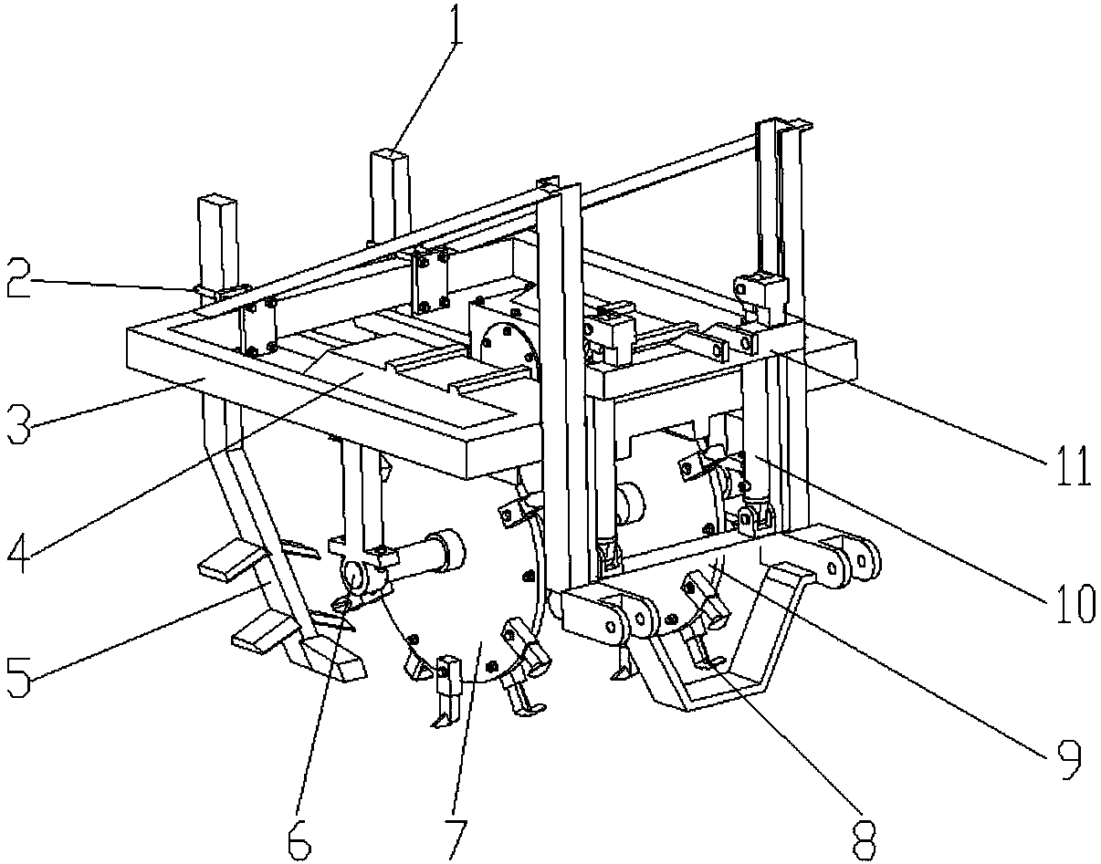
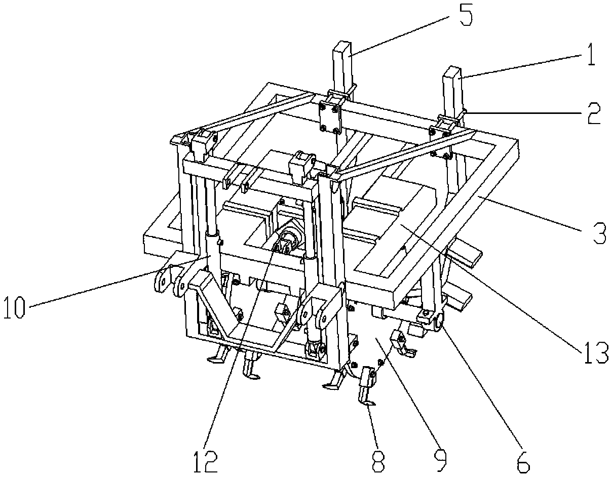
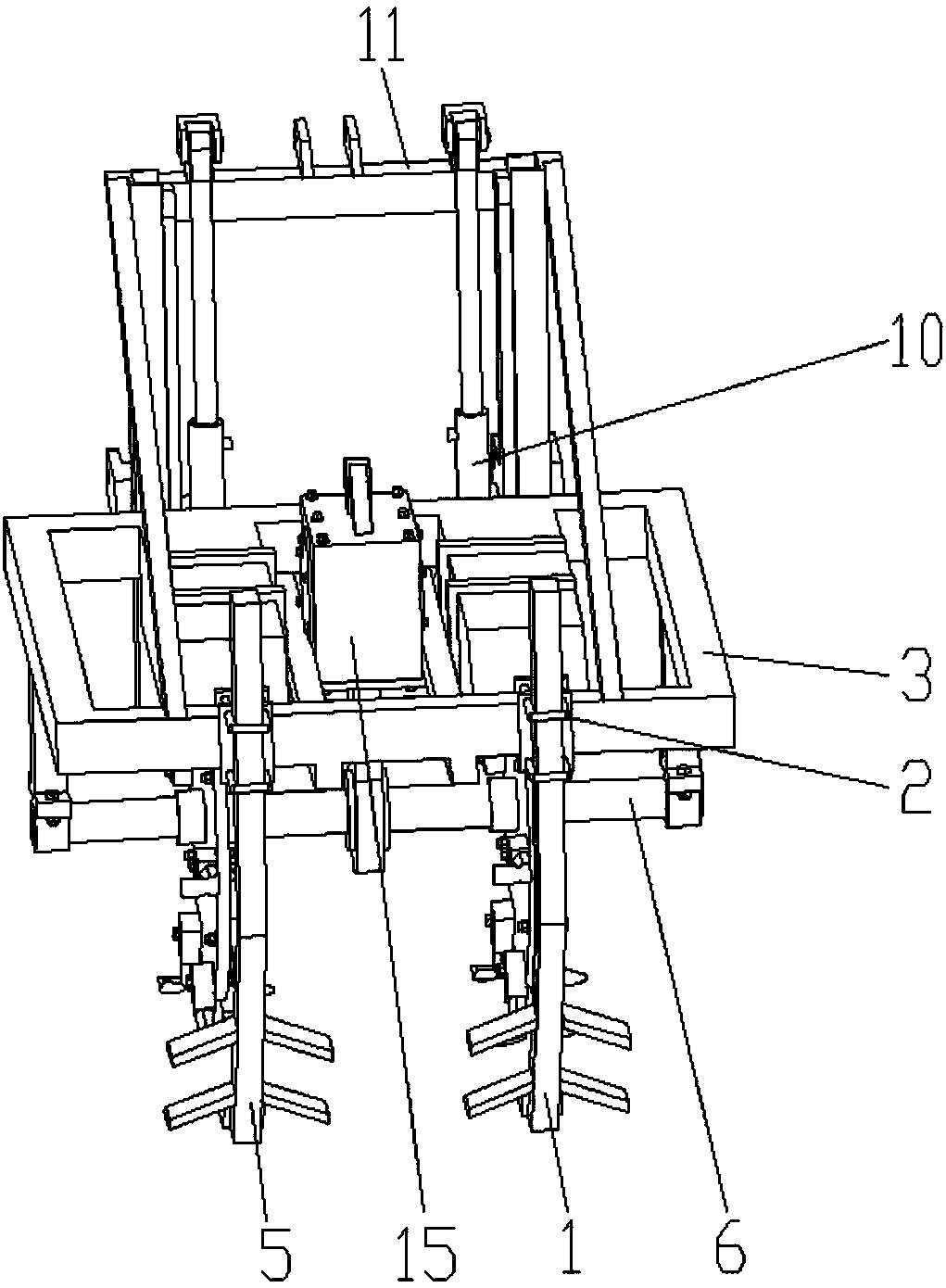
[0015] Such as figure 1 , figure 2 , image 3 , Figure 4 As shown, the lift-adjustable greenhouse subsoiler includes a frame 3, a left double-wing subsoiler 1, a right double-wing subsoiler 5, a gearbox 15, a cutter shaft 6, a left cutterhead 9, and a right cutter Disc 7, left soil retaining cover 13, right soil retaining cover 4 constitute the drag-reducing cutter head assembly, three-point suspension device 11, two hydraulic cylinders 10 are symmetrically hinged at the front end of frame 3, and the upper ends of the two hydraulic cylinders 10 pass through pins It is hingedly installed together with the three-point suspension device 11, and two guide wheels 14 are respectively installed symmetrically on the left and right sides of the three-point suspension device 11. Under the action of two hydraulic cylinders 10, the three-point suspension device 11 can slide up a...


PUM


Abstract

The invention discloses a lifting adjustable greenhouse subsoiler. The lifting adjustable greenhouse subsoiler comprises a frame, a left double-layer-wing subsoiling cutter, a right double-layer-wingsubsoiling cutter, a resistance-reduction cutter head component and a three-point suspension device and is characterized in that the front end of the frame is connected with the three-point suspensiondevice through two symmetrical hydraulic cylinders, the resistance-reduction cutter head component is mounted in the middle of the frame and comprises a gearbox, a cutter shaft, a left cutter head, aright cutter head, a left soil retaining cover and a right soil retaining cover, the gearbox is mounted in the middle of the frame, the output end of the gearbox is connected with the cutter shaft, the left side of the cutter shaft is in key connection with the left cutter head, the left soil retaining cover is arranged right above the left cutter head, the right side of the cutter shaft is in key connection with the right cutter head, the right soil retaining cover is arranged right above the right cutter head, and the left end and the right end of the cutter shaft are hinged to the frame; the left double-layer-wing subsoiling cutter is arranged at the right rear of the left cutter head, and the right double-layer-wing subsoiling cutter is arranged at the right rear of the right cutter head. The lifting adjustable greenhouse subsoiler is compact in structure, low in power consumption and convenient to mount and use.

Description

technical field [0001] The invention relates to the field of facility agriculture subsoiling machinery, in particular to a lift-adjustable greenhouse subsoiler. Background technique [0002] With the rapid development of facility agriculture in my country, the planting area has ranked first in the world, but the degree of mechanization is low, and the subsoiling operation as an important agronomy has not been solved. As we all know, the continuous operation of small and medium-sized agricultural machinery in the greenhouse has caused The large reduction of earthworms and other organisms, the destruction of soil capillaries, the destruction of soil nutrient transport capacity, it is difficult to maintain the demand for water, fertilizer, air and heat for normal growth of plants; The pressure and serious turning of the soil do not meet the needs of crop growth. At present, the subsoilers on the market are only aimed at field operations. Due to the large resistance of subsoiling...

Claims


Application Information

Patent Timeline
Patent Type & Authority Applications(China)
IPC IPC(8): A01B33/02A01B33/08
CPCA01B33/024A01B33/087
Inventor 弋景刚刘江涛孔德刚袁永伟李珊珊
Owner HEBEI AGRICULTURAL UNIV.
Learn More