
Drip irrigation tank for agricultural irrigation

An agricultural irrigation and tank technology, applied in agriculture, application, climate change adaptation, etc., can solve the problems of increased system power consumption, high operating costs, and high manufacturing costs, and achieve reduced operating costs, low production requirements, and low production costs. low effect

Inactive Publication Date: 2018-02-23
李玲
View PDF0 Cites 1 Cited by
  • Summary
  • Abstract
  • Description
  • Claims
  • Application Information

AI Technical Summary

Problems solved by technology

[0014] The purpose of the present invention is to solve the problem that in the existing drip irrigation technology system, a special dripper must be used, but this kind of special dripper has complex structure, high manufacturing cost, short service life, easy blockage, uneven water volume, and cannot be adjusted, and Affecting the problems of increased power consumption of the system and high operating costs, a drip irrigation tank for agricultural irrigation is provided

Method used


Image

  • Drip irrigation tank for agricultural irrigation
  • Drip irrigation tank for agricultural irrigation
  • Drip irrigation tank for agricultural irrigation

Examples


Embodiment Construction

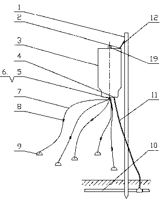
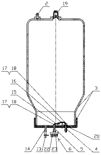
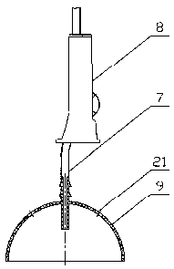
[0043] see figure 1 , 2 , the present invention has airtight tank body 3, particularly: the top of tank body 3 is equipped with ventilation check valve 19 (comprising a valve body and a float ball contained in the valve body, the top of the valve body has a vent hole, can two-way ventilation); at the bottom of the tank body 3, an inlet pipe 4 and an outlet pipe 5 are installed, and a linkage switch is installed between the inlet pipe 4 and the outlet pipe 5. The linkage switch includes a support 15 on which a lever is mounted. Type valve stem 16, the two ends of the valve stem 16 are designed with a closed structure, wherein one end of the closed structure is arranged facing the water inlet pipe 4, and the other end is arranged facing the water outlet pipe 5, and the side of the valve stem 16 close to the water inlet pipe 4 is equipped with A tension spring 20, and a distributor 6 is connected to the outer end of the outlet pipe 5; the distributor 6 has a distribution chamber...


PUM


Abstract

The invention relates to an agricultural irrigation device, in particular to a drip irrigation tank for agricultural irrigation. The drip irrigation tank for agricultural irrigation comprises a sealedtank body, and is characterized in that: a ventilation spill preventing valve is arranged on the top of the tank body, a water inlet pipe and a water outlet pipe are arranged at the bottom of the tank body, and a gang switch is arranged between the water inlet pipe and the water outlet pipe; the gang switch comprises a support, the support is provided with a lever-type valve rod, and two ends ofthe valve rod are provided with closed structures according to design; the closed structure at one end of the valve rod is arranged opposite to the water inlet pipe, the closed structure at the otherend of the valve rod is arranged opposite to the water outlet pipe, and a tension spring is arranged the side, near to the water inlet pipe, of the valve rod; and a distributor is arranged at the outer end of the water outlet pipe, each branch joint of the distributor is connected with a delivery hose, and each delivery hose is provided with a water flow regulator. According to the drip irrigationtank for agricultural irrigation, the problems that since a special emitter is adopted for drip irrigation, an existing agricultural drip irrigation system has the disadvantages of incident clogging,no regulation of the water flow, a complicated structure of the emitter, high manufacturing cost, short service life, large power consumption of the system and the like are solved, and the drip irrigation tank for agricultural irrigation can be widely used in crop irrigation.

Description

technical field [0001] The invention relates to an agricultural irrigation device, in particular to a drip irrigation tank for agricultural irrigation. Background technique [0002] An important branch of modern agricultural irrigation is the drip irrigation technology system, which includes a water pump station, main water pipe, water distribution pipe, and multiple special drippers installed on the water distribution pipe. The structure of this dripper is very complicated and the manufacturing accuracy The requirements are high (mainly because the drippers are installed in a high-pressure system to realize drip irrigation). At present, the drippers used in China mainly rely on imports. There are a few imitations in China, but the technology is not up to standard. The existing problems of special drippers both at home and abroad are: [0003] ⑴The dripper is easy to block [0004] Clogging is a major problem with drip irrigation systems. Under normal circumstances, becau...

Claims


Application Information

Patent Timeline
IPC IPC(8): A01G25/02
CPCA01G25/023Y02A40/22
Inventor 李玲
Owner 李玲
Learn More