Method for cleaning dust-mixed waste gas
A waste gas and dust technology, applied in the field of environmental protection equipment, can solve the problems of reduced air intake in the pipeline, easy blockage of the pipeline, and reduced efficiency, and achieve the effect of increased speed, good mixing effect, and avoiding the blockage of the intake pipe
Active Publication Date: 2018-02-23
宁波江北清纬环保科技有限公司
View PDF4 Cites 0 Cited by
- Summary
- Abstract
- Description
- Claims
- Application Information
AI Technical Summary
Problems solved by technology
However, dust with a smaller particle size needs a filter with a larger mesh to filter, and a filter with a larger mesh has a better blocking effect on exhaust gas, and the time for exhaust gas to pass through the filter increases, and the efficiency will be further reduced
Method used
View moreImage
Smart ImageViewing Examples
Examples
Embodiment Construction
[0027] Below in conjunction with accompanying drawing and specific embodiment the present invention will be described in further detail:
Login to View More PUM
 Abstract
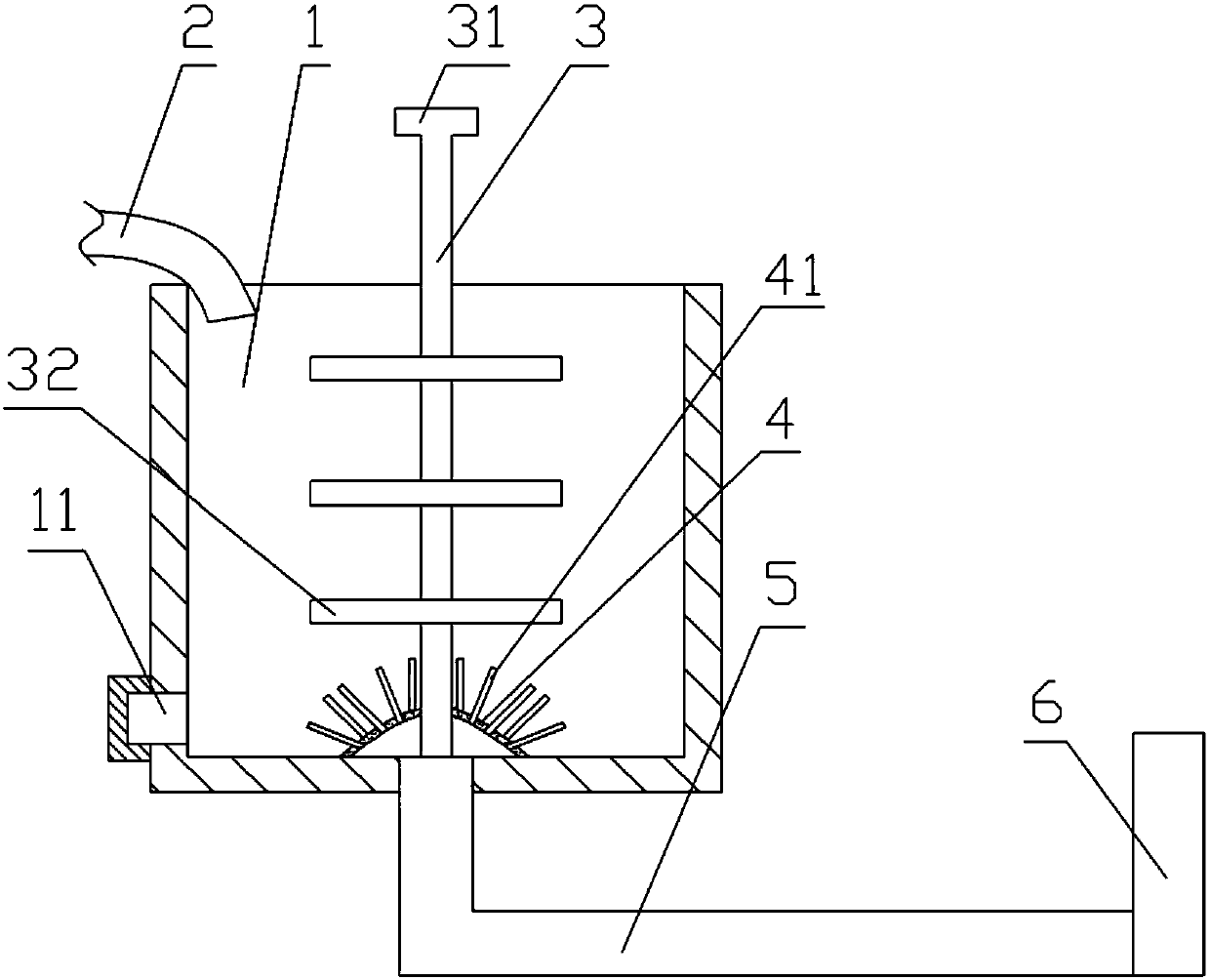
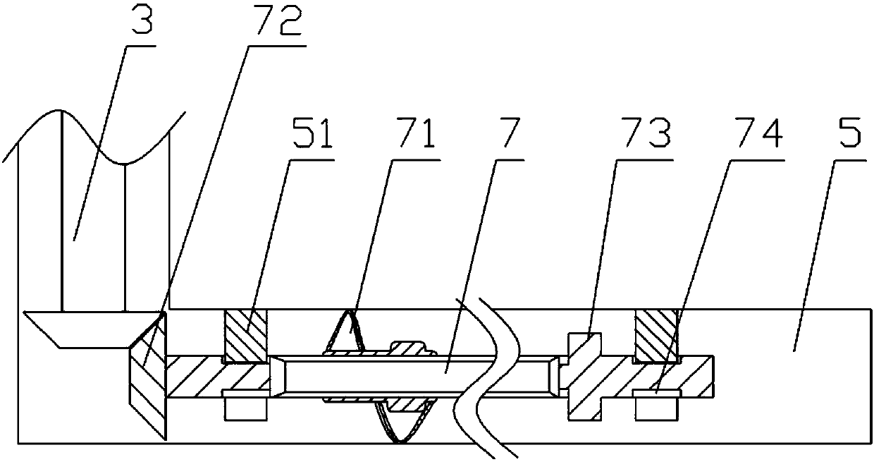
The invention relates to the field of environment-protecting equipment, and particularly discloses a method for cleaning dust-mixed waste gas. A cleaning device is used for cleaning and comprises a machine frame, a water tank, a stirring mechanism and a gas inlet mechanism; a water outlet is formed in the lower part of the water tank; a liquid inlet pipe is fixed on the machine frame; the gas inlet mechanism comprises a gas inlet pipe, a rotating shaft and a spiral blade; the gas inlet pipe is fixed with the water tank; the rotating shaft is arranged in the length direction of the gas inlet pipe; a fixed piece is arranged at the periphery of the rotating shaft; a first bevel gear and a rotating blade are fixed on the rotating shaft; the spiral blade is positioned at the periphery of the rotating shaft; the spiral blade is connected with a rotating shaft key; the stirring mechanism comprises a stirring shaft and a stirring blade; the upper end of the stirring shaft is rotatably connected with the machine frame; a second bevel gear is fixed at the lower end of the stirring shaft; the stirring blade is fixed on the stirring shaft. The cleaning method comprises the following steps: (1)preparing a cleaning liquid; (2) filtering; (3) cleaning; (4) changing the liquid; (5) discharging the liquid. According to the scheme, blockage of the gas inlet pipe can be avoided.
Description
technical field [0001] The invention relates to the field of environmental protection equipment, in particular to a gas cleaning device. Background technique [0002] The current factories will generate waste gas during the production process. These waste gases contain a large amount of toxic and harmful gases and dust with different particle sizes. Great damage to people's health, so it is necessary to purify the exhaust gas before discharging it. [0003] The traditional purification method is to filter the gas to remove relatively large dust in the exhaust gas; then add the reagent to water to form a solution, and pass the exhaust gas into the solution, the toxic and harmful gas contacts the solution and reacts with the reagent, so that it can be removed Toxic and harmful gases in the exhaust gas. However, dust with a smaller particle size needs a filter with a larger mesh to filter, and a filter with a larger mesh has a better blocking effect on exhaust gas, and the ti...
Claims
Login to View More Application Information
Patent Timeline
 IPC IPC(8): B01D50/00B01D53/86B01D53/78B01D53/14
CPCB01D53/14B01D53/78B01D53/86B01D50/60
Inventor 王健
Owner 宁波江北清纬环保科技有限公司
Features
- R&D
- Intellectual Property
- Life Sciences
- Materials
- Tech Scout
- Unparalleled Data Quality
- Higher Quality Content
- 60% Fewer Hallucinations
Learn More Browse by: Latest US Patents, China's latest patents, Technical Efficacy Thesaurus, Application Domain, Technology Topic, Popular Technical Reports.
© 2025 PatSnap. All rights reserved.Legal|Privacy policy|Modern Slavery Act Transparency Statement|Sitemap|About US| Contact US: help@patsnap.com


