Check patentability & draft patents in minutes with Patsnap Eureka AI!

Numerical control machine tool

A technology of CNC lathe and bed, which is applied in the direction of metal processing machinery parts, turning equipment, maintenance and safety accessories, etc. It can solve the problems of untimely debris disposal and the impact of processing debris, etc.

Inactive Publication Date: 2018-02-23
秦科
View PDF5 Cites 0 Cited by
  • Summary
  • Abstract
  • Description
  • Claims
  • Application Information

AI Technical Summary

Problems solved by technology

The lathes currently on the market do not deal with the debris after machining the workpiece in time, resulting in the processing being affected by the debris

Method used


Image

  • Numerical control machine tool

Examples


Embodiment Construction

[0010] The principles and features of the present invention are described below in conjunction with the accompanying drawings, and the examples given are only used to explain the present invention, and are not intended to limit the scope of the present invention.

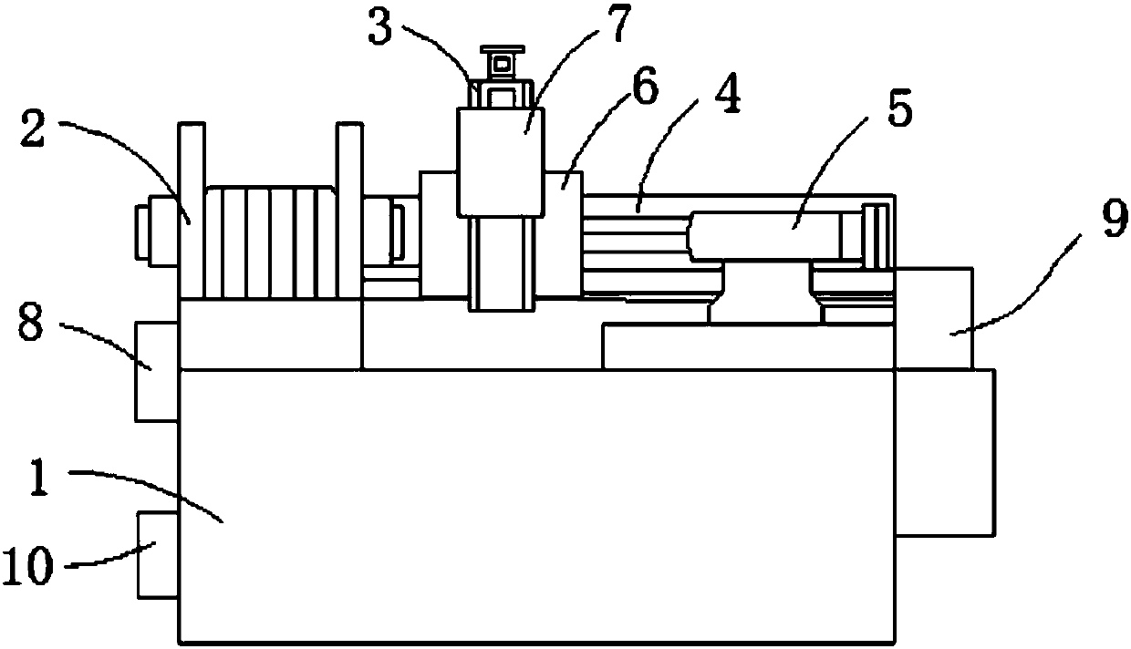
[0011] Such as figure 1 As shown, a chip removal CNC lathe includes a bed 1, a headstock 2, a Z-axis guide rail 3, an X-axis guide rail 4 and a tailstock 5, and the headstock 2 and the X-axis guide rail 4 are fixedly placed on the bed The upper end of the body 1, the X-axis guide rail 4 is on one side of the headstock 2, the X-axis guide rail 4 is equipped with a laterally movable X-axis feed table 6, and the Z-axis guide rail 3 is fixed on the On the X-axis feed table 6, the Z-axis guide rail 3 is equipped with a vertically movable Z-axis feed table 7, and the guide grooves of the X-axis guide rail 4 and the Z-axis guide rail 3 are all made of graphene. In this way, the tailstock 5 is placed on the side of the X-a...


PUM


Abstract

The invention relates to a chip removing numerical control machine tool. The chip removing numerical control machine tool comprises a tool body, a spindle box, a Z-axis guide rail, an X-axis guide rail and a tailstock; the spindle box and the X-axis guide rail are both fixedly placed at the upper end of the tool body; the X-axis guide rail is located on one side of the spindle box; an X-axis feeding table capable of moving horizontally is mounted on the X-axis guide rail; the Z-axis guide rail is fixedly placed on the X-axis feeding table; a Z-axis feeding table capable of moving vertically ismounted on the Z-axis guide rail; guide grooves of the X-axis guide rail and the Z-axis guide rail are both made of graphene; the tailstock is placed on the side, away from the spindle box, of the X-axis guide rail; and an ultrasonic generation device is arranged on one side of the machine tool, and an air suction device is arranged on the other side of the machine tool. Compared with the prior art, according to the chip removing numerical control machine tool, the chip removing efficiency is promoted.

Description

technical field [0001] The invention relates to the field of numerical control machining, in particular to a numerical control machine tool. Background technique [0002] The guide rail of CNC lathe has a very important position in the whole lathe, and it largely determines the rigidity, precision and precision retention of the lathe. The main task of the guide rail is to play a role in carrying the supporting parts and guiding the execution parts. The lathes currently on the market do not deal with the debris after machining the workpiece in time, which causes the processing to be affected by the debris. Contents of the invention [0003] The purpose of the present invention is to provide a numerically controlled machine tool. The technical problem to be solved is: the lathes on the market do not deal with the debris after processing the workpiece in time, which causes the processing to be affected by the debris. [0004] The technical solution of the present invention ...

Claims


Application Information

Patent Timeline
IPC IPC(8): B23Q11/00B23B25/00
CPCB23Q11/0046B23B25/00
Inventor 秦科
Owner 秦科
Features
  • R&D
  • Intellectual Property
  • Life Sciences
  • Materials
  • Tech Scout
  • Unparalleled Data Quality
  • Higher Quality Content
  • 60% Fewer Hallucinations
Learn More