Expansion tank used by double systems of new energy automobile in common

A new energy vehicle, expansion tank technology, applied in the direction of vehicle components, component optimization, and the arrangement of the cooling combination of the power unit, can solve the problems of limited layout space of the engine compartment, high maintenance and maintenance costs, and unfavorable vehicle bodies, to simplify the first time. The effect of filling operation, convenient later maintenance and saving design quantity

Active Publication Date: 2018-02-23
DONGFENG MOTOR CORP HUBEI
View PDF9 Cites 7 Cited by
  • Summary
  • Abstract
  • Description
  • Claims
  • Application Information

AI Technical Summary

Problems solved by technology

The layout space of the engine compartment is limited, and more expansion tanks will make the layout of the engine compartment more difficult, increasing the assembly and filling man-hours of the automobile assembly line, and the daily maintenance costs are high, which is not conducive to the weight loss of the vehicle body
[0003] There are already arrangements for integrating the two expansion tanks of electric vehicles, such as Chinese patents with application numbers 201320498226. Save space in the engine room, but these expansion tanks need to design two sets of coolant filling ports and two sets of liquid level observation lines, the structure is complex, and the filling process is cumbersome

Method used


Image

  • Expansion tank used by double systems of new energy automobile in common
  • Expansion tank used by double systems of new energy automobile in common
  • Expansion tank used by double systems of new energy automobile in common

Examples


Embodiment Construction

[0019] The present invention will be further described in detail below in conjunction with the accompanying drawings to facilitate a clearer understanding of the present invention, but the present invention is not limited to the following specific embodiments.

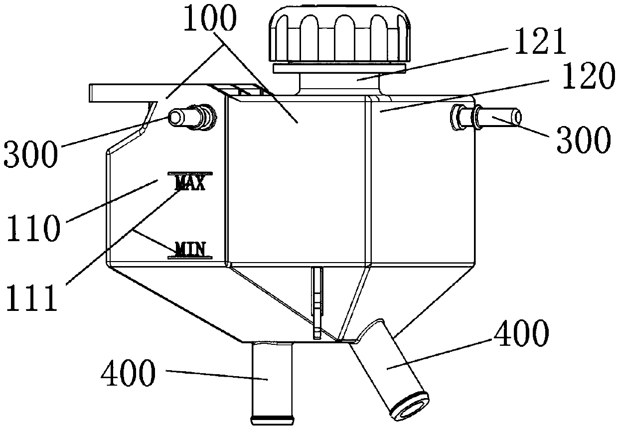
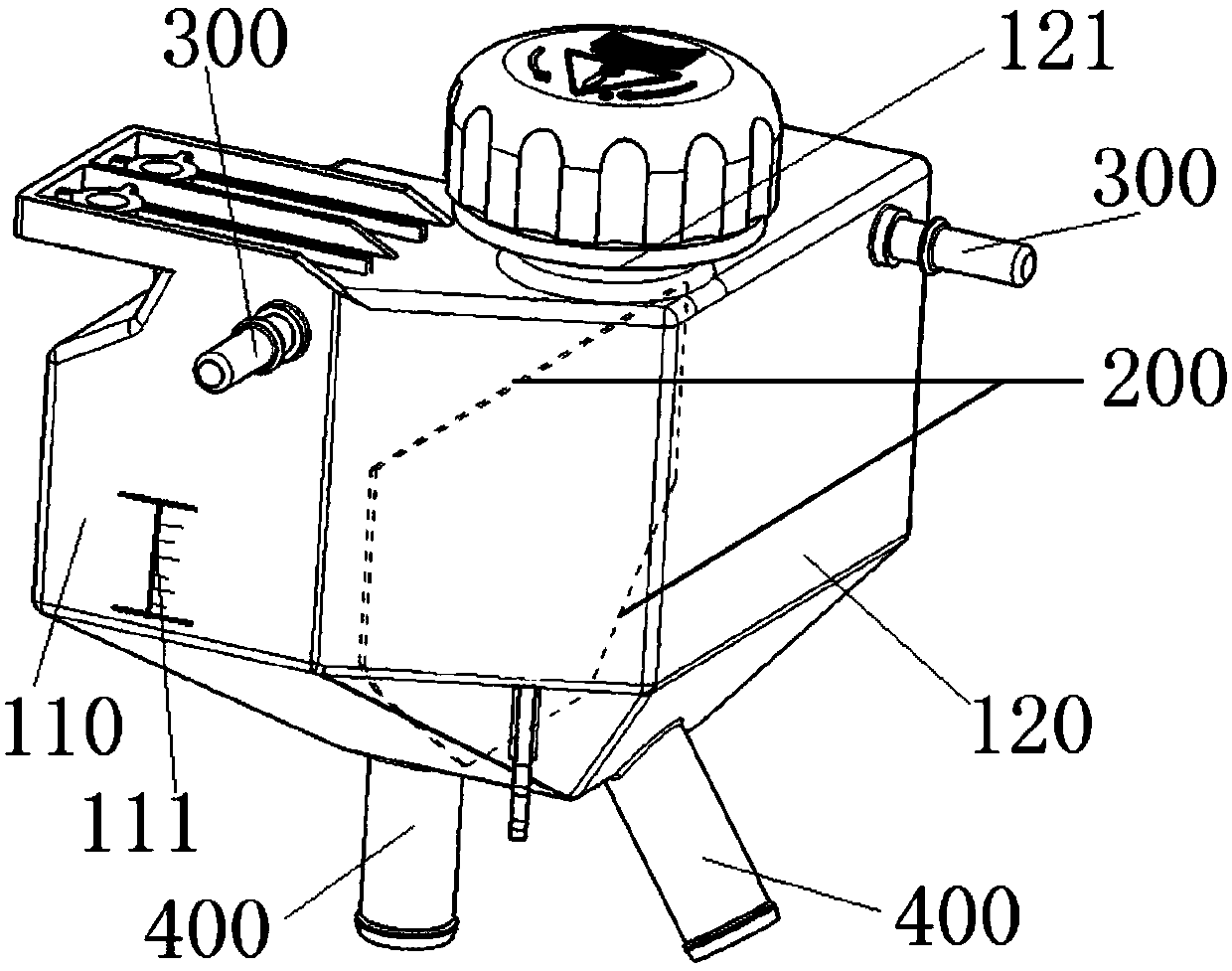
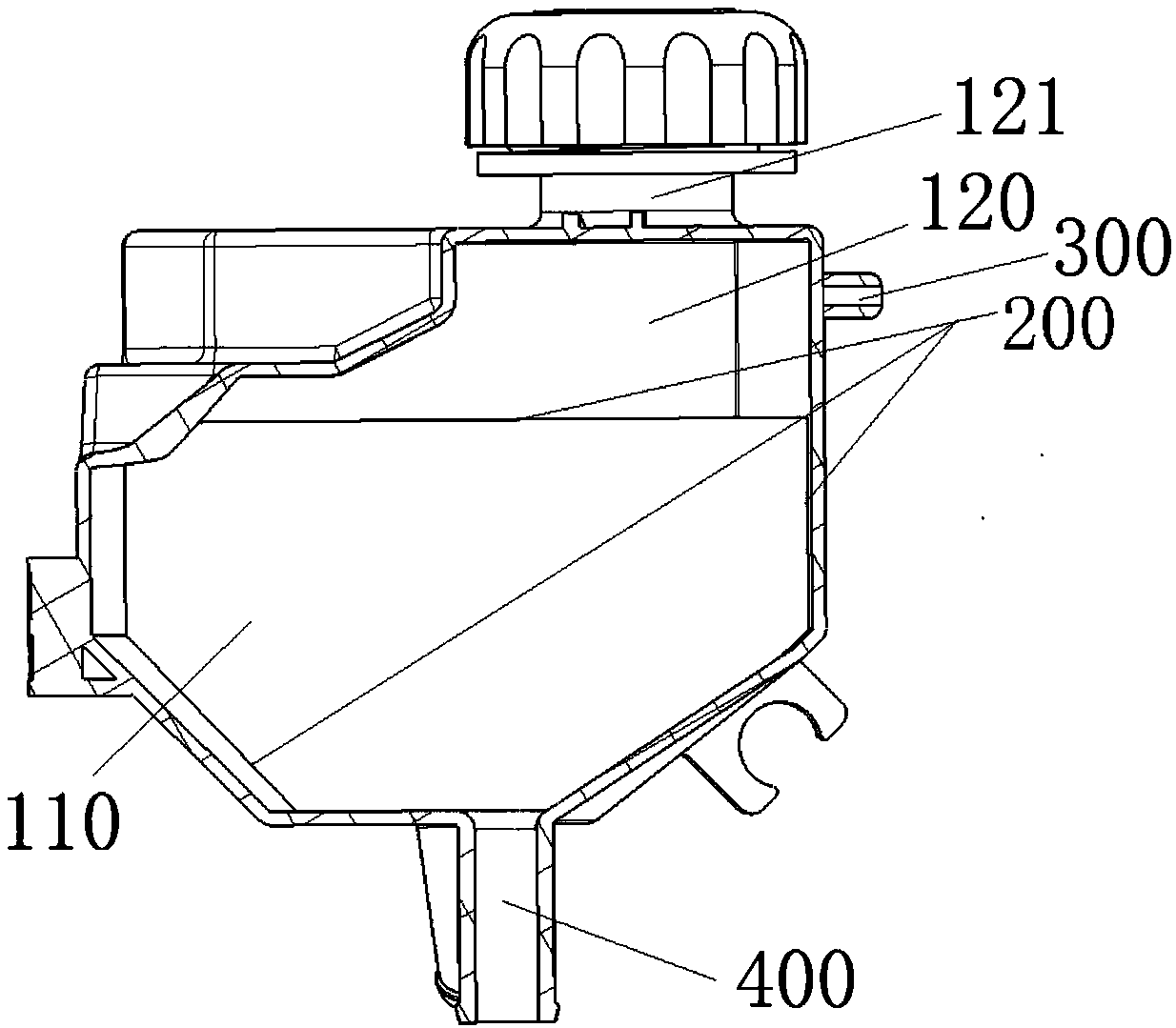
[0020] Such as figure 1 , figure 2 with image 3 As shown, a dual-system shared expansion water tank for a new energy vehicle of the present invention includes an expansion water tank 100 and a partition 200. The partition 200 is vertically arranged and divides the interior of the expansion tank 100 into two separate chambers connected with the upper part and the lower part respectively. It is a high temperature chamber 110 and a low temperature chamber 120. The high temperature chamber 110 communicates with the driving motor cooling system, and the low temperature chamber 120 communicates with the power battery cooling system; the bottom and two sides of the partition 200 are connected to the bottom and two sides of the e...


PUM


Abstract

The invention discloses an expansion tank used by double systems of a new energy automobile in common. The expansion tank comprises an expansion tank body and a separation plate, gas removal openingsare formed in the upper portions of the two sides of the expansion tank body respectively, and water return openings are formed in the bottoms of the two sides of the expansion tank body respectively,and the separation plate is a separation layer capable of insulating heat. The separation plate is vertically arranged and divides the interior of the expansion tank body into a high-temperature chamber and a low-temperature chamber, the upper portion of the high-temperature chamber and the upper portion of the low-temperature chamber are communicated, and the lower portion of the high-temperature chamber and the lower portion of the low-temperature chamber are separated. A cooling liquid filling opening is formed in a top cover of the low-temperature chamber, and a liquid level indicating window is arranged on the side face of the high-temperature chamber. The expansion tank is filled with cooling liquid from the unique cooling liquid filling opening till the low-temperature chamber is full of the cooling liquid, the cooling liquid continues to be added to the highest liquid level indicating position of the high-temperature chamber, the cooling liquid is stopped from being added, thechambers on the two sides of the separation plate are both filled with the cooling liquid meeting the work required volume, the cooling liquid in the two chambers is isolated by the separation platecapable of insulating heat and can independently work without disturbing each other, the primary filling operation of a final assembly line is simplified, and later maintenance is convenient.

Description

Technical field [0001] The invention belongs to the technical field of automobile auxiliary systems, in particular to a dual-system shared expansion water tank for a new energy automobile. Background technique [0002] New energy vehicles are an emerging field in the automotive industry, mainly electric vehicles and hybrid vehicles. The working water temperature requirements of the power modules of the two vehicles are quite different, and the vehicle power system needs to be equipped with 2 to 3 sets of independent cooling System, each cooling system needs to be equipped with an expansion tank. For example, an electric vehicle driven only by electricity needs to use one expansion tank for the driving motor cooling system and the power battery cooling system, while a hybrid vehicle driven by a gasoline-electric hybrid requires three or more. The layout of the engine compartment is limited, and a larger number of expansion tanks will increase the difficulty of the layout of the e...

Claims


Application Information

Patent Timeline
Patent Type & Authority Applications(China)
IPC IPC(8): B60K11/02
CPCB60K11/02Y02T10/88
Inventor 万鑫陈涛晏晓雷万嘉明王乐
Owner DONGFENG MOTOR CORP HUBEI
Why Eureka
Try Eureka