High-temperature-resistant clamping mechanism

A clamping mechanism and high-temperature-resistant technology, applied in the direction of conveyor objects, furnaces, lighting and heating equipment, etc., can solve the problems of limiting automatic processing, etc., and achieve the effects of high work efficiency, good stability and wide applicability

Inactive Publication Date: 2018-02-23
SHENZHEN JUNYIHAO TECH
View PDF0 Cites 1 Cited by
  • Summary
  • Abstract
  • Description
  • Claims
  • Application Information

AI Technical Summary

Problems solved by technology

[0002] At present, a large number of high-temperature gripping devices used in the market can only transfer products or carriers from room temperature to high-temperature environments, transfer from high-temperature environments to room temperature environments, or only move products in high-temperature environments. Or the carrier performs a simple propulsion action, but it has never been able to perform complex actions such as clamping and moving in a high-temperature environment, which limits automated processing in a high-temperature environment

Method used


Image

  • High-temperature-resistant clamping mechanism
  • High-temperature-resistant clamping mechanism

Examples


Embodiment Construction

[0020] The present invention will be further described below in conjunction with the accompanying drawings and specific embodiments. Terms such as "upper", "lower", "left", "right", "middle" and "one" quoted in the preferred embodiment are only for convenience of description, and are not used to limit the scope of the present invention. The scope of implementation and the change or adjustment of its relative relationship shall also be regarded as the scope of implementation of the present invention without substantive changes in technical content.

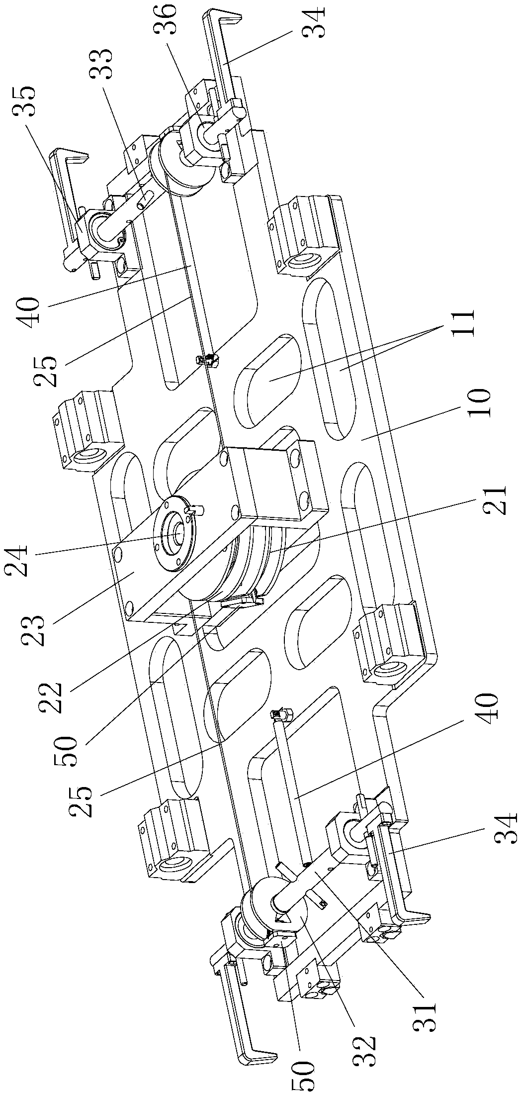
[0021] See figure 1 and figure 2 , a high-temperature-resistant clamping mechanism designed in a preferred embodiment of the present invention, which mainly includes: a plate frame 10, a pulley assembly and a jaw assembly, and the pulley assembly and the jaw assembly are installed on the plate frame 10. The following describes each Components and their connections.

[0022] Specifically, the plate frame 10 is made of a flat pla...


PUM


Abstract

A high-temperature-resistant clamping mechanism, including: a plate frame, a pulley assembly and a jaw assembly, the pulley assembly is installed in the middle of the plate surface of the plate frame, and the pulley assembly includes: an inverted U-shaped positioning frame, and the lower and upper coaxially installed in the positioning frame The main pulley and the slave pulley, the main pulley is wound with a driving wire rope, and the slave pulley is symmetrically wound with two driven wire ropes protruding in opposite directions; two sets of jaw assemblies are symmetrically installed on the plate frame along the direction of the driven wire rope On both sides, the jaw assembly includes: a rotating shaft, a rotating wheel fixed on the rotating shaft, a connecting rod inserted vertically in the middle of the rotating shaft, and jaws fixedly connected to both ends of the rotating shaft. On the seat, one end of the driven wire rope is correspondingly wound on the running wheel, and the lower end of the connecting rod protruding from the rotating shaft is connected with a stretched spring. The invention realizes the grabbing action of the product or the carrier under the high temperature environment, has excellent high temperature resistance performance, high working efficiency, low failure rate, and is suitable for various working environments.

Description

technical field [0001] The invention relates to a clamping mechanism in the field of mechanical automation, which is mainly used for the clamping action of carriers in high-temperature environments such as the drying process and hot bending process of various electronic products, glass products and metal parts. Background technique [0002] At present, a large number of high-temperature gripping devices used in the market can only transfer products or carriers from room temperature to high-temperature environments, transfer from high-temperature environments to room temperature environments, or only move products in high-temperature environments. Or the carrier performs a simple propulsion action, but it has never been able to perform complex actions such as clamping and moving in a high-temperature environment, which limits automated processing in a high-temperature environment. [0003] Therefore, in view of the prior art, how to design and develop a clamping mechanism tha...

Claims


Application Information

Patent Timeline
IPC IPC(8): B65G47/90B65G49/06
CPCB65G47/90B65G49/061
Inventor 杨春海李松伟周科
Owner SHENZHEN JUNYIHAO TECH
Why Eureka
Try Eureka