Hydropower station draft tube structure

A technology for draft tubes and hydropower stations, which is applied in the directions of hydropower stations, hydroelectric power generation, water conservancy projects, etc., can solve the problems of increasing the amount of excavation works and concrete works of the bottom plate, affecting the normal use of draft tubes, and large temperature stress of concrete, etc. The effect of reducing the amount of concrete works, reducing the amount of excavation works, and reducing the lifting pressure

Pending Publication Date: 2018-02-23
POWERCHINA CHENGDU ENG
View PDF5 Cites 0 Cited by
  • Summary
  • Abstract
  • Description
  • Claims
  • Application Information

AI Technical Summary

Problems solved by technology

[0006] 1. The size of the draft tube is large, which often leads to a large thickness of the bottom plate of the draft tube, which increases the amount of floor excavation and concrete engineering;
[0007] 2. For the thicker floor, the temperature stress of the concrete is too large during the construction period, and at the same time, it is strongly restrained by the foundation, which often leads to cracking of the concrete of the floor and affects the normal use of the draft tube;

Method used


Image

  • Hydropower station draft tube structure
  • Hydropower station draft tube structure
  • Hydropower station draft tube structure

Examples


Embodiment Construction

[0031] The present invention will be further described below in conjunction with the accompanying drawings and specific embodiments.

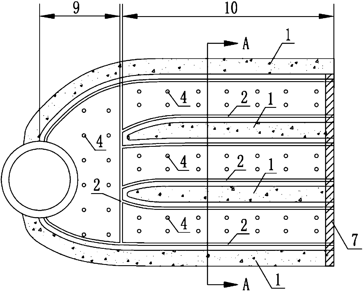
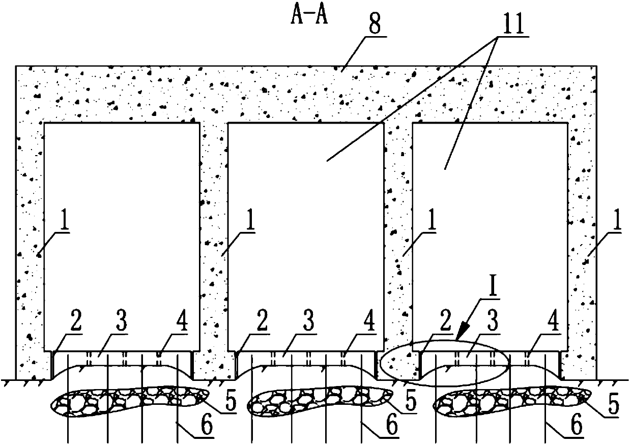
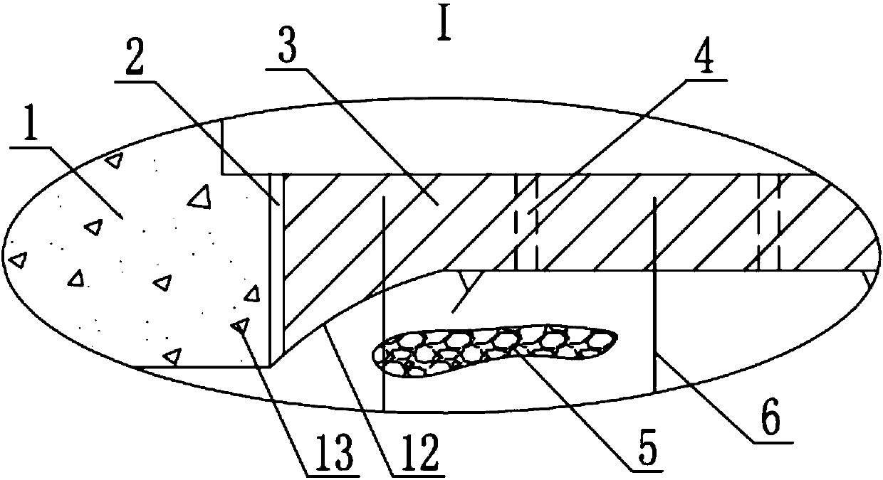
[0032] Such as figure 1 to attach Figure 4 As shown in , the draft tube structure of the hydropower station in the present invention refers to the water guide channel structure immediately adjacent to the outlet of the impact turbine runner, which guides the water flowing out of the turbine runner to connect with the downstream tail water. The draft tube structure of a hydropower station according to the present invention includes a pier wall 1 and a bottom plate 3 ; wherein, a structural joint 2 is provided between the bottom plate 3 and the pier wall 1 . The function of the structural joint 2 is to separate the base plate 3 from the pier wall 1, so that the concentrated load on the pier wall 1 can no longer be distributed by the base plate, thereby reducing the internal stress of the base plate 3 and reducing its required thickness. Reduc...


PUM


Abstract

The invention discloses a hydropower station draft tube structure, belongs to the field of hydropower station workshop building structures and provides a draft tube structure suitable for a high-flowhydroelectric generation workshop. The thickness of an inner bottom plate of a draft tube can be decreased, the excavating engineering amount and the concrete engineering amount can be decreased, construction is simplified, and meanwhile the problem of cracking, caused by temperature stress in the pouring process, of the bottom plate is avoided. The draft tube structure comprises a pier wall and the bottom plate, and a structural seam is formed between the bottom plate and the pier wall. According to the hydropower station draft tube structure, the structural seam is formed between the bottomplate and the pier wall so that separation between the bottom plate and the pier wall can be achieved, the bottom plate does not need to disperse concentrated load borne by the pier wall any longer, thus the thickness of the bottom plate can be decreased, and the excavating engineering amount and the concrete engineering amount can be decreased; meanwhile the cracking condition, caused by the temperature stress in the concrete construction process, of the bottom plate can be avoided; and additionally, separate construction of the bottom plate and the pier wall can further be facilitated, the construction difficulty is lowered, and later-period work of overhauling, maintaining, replacing and the like of the bottom plate is reduced.

Description

technical field [0001] The invention relates to the field of building structures of hydroelectric power stations, in particular to draft tube structures in hydropower stations. Background technique [0002] Draft tube is one of the important components of hydropower plant. The draft tube is a water guide channel structure immediately connected to the outlet of the impact turbine runner, which guides the water flowing out of the turbine runner to connect with the downstream tail water, and can recover part of the kinetic energy of the water flowing out of the runner; usually, along the direction of water flow, The draft tube is generally divided into a cone section, an elbow section, and a diffuser section. The structural design of the draft tube often affects the functional use of the entire power plant. [0003] Currently in the draft tube structure, such as attached Figure 5 As shown in , it is usually a pipe structure integrated by pouring concrete such as roof, floor ...

Claims


Application Information

Patent Timeline
IPC IPC(8): E02B9/02
CPCE02B9/022Y02E10/20
Inventor 幸享林肖平西张勇廖成刚彭薇薇
Owner POWERCHINA CHENGDU ENG
Why Eureka
Try Eureka