
Rotary drilling machine with adjustable perpendicularity
A technology of verticality and drilling machine, which is applied in the direction of rotary drilling rig, rotary drilling, percussion drilling, etc., which can solve the problems of low operating efficiency, affecting the horizontal and vertical positioning of the robot, and no guarantee of safety.
- Summary
- Abstract
- Description
- Claims
- Application Information
AI Technical Summary
Problems solved by technology
Method used
Image

Examples
Embodiment 1
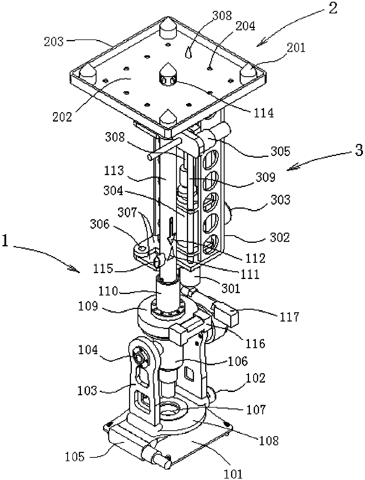
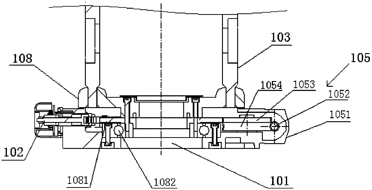
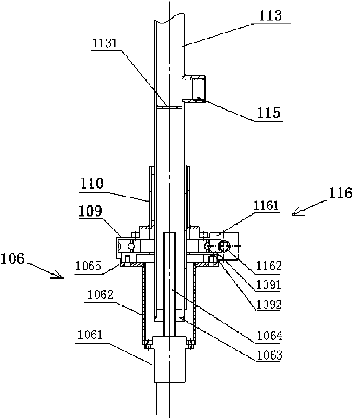
[0045] See figure 1 —— Figure 7 The rotary drilling machine with adjustable verticality provided by the present invention comprises a verticality adjustment device 1, a drilling positioning device 2 and a drilling device 3; the verticality adjustment device 1 includes a base 101 with a vertical axis, a The axis rotates and is provided with the direction turning mechanism of level instrument 107, is hinged on described direction turning mechanism by horizontal shaft 104 and is provided with the turning mechanism of vertical instrument; Described direction turning mechanism comprises the first rotary disk 108 that rotates around vertical axis, The bracket 103 arranged on the first rotary disk 108, the horizontal axis 104 is hinged on the bracket 103, the level 107 is arranged on the first rotary disk 108, and the base 101 is provided with a driving first The first electric driving device 105 that the rotary disk 108 rotates and the screw locking device 102 that cooperates with...
Embodiment 2
[0051] See Figure 12 , the difference between this embodiment and embodiment 1 is:
[0052] 1) The slewing mechanism is different. The slewing mechanism in this embodiment removes the second turntable 109 provided on the first electric telescopic mechanism 106 and the sleeve 110 and the third turntable that drives the second turntable 109 to rotate. The electric driving device 116 includes the second electric driving device 117 arranged on the bracket 103 to drive the rotation of the horizontal shaft 104, the first electric telescopic mechanism 106 provided on the horizontal shaft 104, the first electric telescopic mechanism 106 provided on the first electric telescopic The casing 110 on the mechanism 106, the hollow vertical rod 113 that is arranged in the casing 110 and connected with the first electric telescopic mechanism 106, the casing 110 is arranged on the first electric telescopic mechanism 106 through a flange 1101 on the flange 1065 of the housing 1062;
[0053] ...
Embodiment 3
[0059] See Figure 14 , Figure 15 , the present embodiment comprises a verticality adjustment device 1, a mechanical arm 4 located on the verticality adjustment device 1 and a drilling device 3 located on the mechanical arm 4; the verticality adjustment device 1 in the present embodiment and embodiment 1 The difference is that the rotary mechanism in the verticality adjustment device 1 is different. In this embodiment, the first electric telescopic mechanism 106 is not provided in the rotary mechanism, and the sleeve and vertical rod are not provided on the second rotary disk 109, but the The second rotary disk 109 is arranged on the transverse axis 104; the mechanical arm 4 includes a support 401, a crank arm 403 arranged on the support 401 through joints, a joint between the crank arms, and a joint that drives each joint to rotate. The motor 402 , the support 401 is arranged on the second turntable 109 in the verticality adjustment device 1 , and the curved arm 403 is conn...
PUM
 Abstract
Description
Claims
Application Information