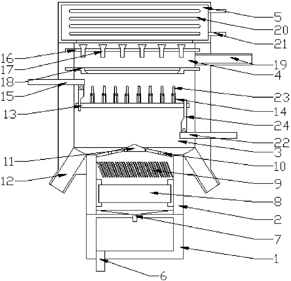
Splitter plate chemical fiber raw material particle dryer

A particle drying and separating plate technology, which is applied in drying chamber/container, drying solid material, drying gas arrangement, etc., can solve the problems of large area and noise of fluidized dryer, and achieve good environmental protection effect and noise. Low, improve the effect of contact area

CN107726789AInactive Publication Date: 2018-02-23杨芳
0 Cites 1 Cited by

Patent Information

Authority / Receiving Office
CN · China
Patent Type
Applications(China)
Current Assignee / Owner
Publication Date
2018-02-23
Estimated Expiration
Not applicable · inactive patent

Smart Images

  • Figure 1
    Figure 1
Patent Text Reader

Abstract

The invention relates to a dryer for chemical fiber raw material particles with a partition plate, which includes a negative pressure chamber, a drainage chamber, a drying chamber, a spray chamber and an air storage chamber; wherein the negative pressure chamber includes a negative pressure tank, which is connected to the On the bottom end of the drainage cavity, the top end of the drainage cavity is provided with a damper; the drying cavity is connected to the top of the drainage cavity through the damper, and the bottom of the drying cavity is provided with a discharge port; the inside of the drying cavity is provided with a drying tray, and the drying tray The upper linear array is provided with a number of partitions connected by rotation. The inner wall of the drying chamber is also symmetrically equipped with a top push rod and a bottom push rod. The end of the top push rod is connected to the spring plate A, and the end of the bottom push rod is connected to B. , the spring plate A and the spring plate B are connected to the bottom support plate; the injection chamber is connected to the top of the drying chamber, the side wall of the injection chamber is provided with a feed pipe, the bottom of the injection chamber is provided with a support plate, and an array of pressure relief valves is arranged on the support plate; The air chamber is located on the top of the injection chamber, and several heating plates are arranged in array in the air storage chamber.
Need to check novelty before this filing date? Find Prior Art

Description

technical field

[0001] The invention relates to a dryer for chemical fiber raw material granules with a partition plate, which belongs to the field of chemical fiber granule drying. Background technique

[0002] Chemical fiber granule raw materials are generally dried by a fluidized dryer. Because the fluidized dryer needs a hot air mechanism and an exciting mechanism, it occupies a large area and uses a lot of noise, and the fluidized dryer needs to be equipped with an air duct. And other auxiliary mechanisms, the cost is higher, also can produce waste heat discharge, do not meet the requirement of environmental protection. Contents of the invention

[0003] The technical problem to be solved by the present invention is: to overcome the technical problems of the fluidized dryer occupying a large area and making a lot of noise in the prior art, and to provide a dryer for chemical fiber raw material particles with partition plates.

[0004] The technical solution adopted b...

Examples

Embodiment Construction

[0015] The present invention is described in further detail now in conjunction with accompanying drawing. These drawings are all simplified schematic diagrams, which only illustrate the basic structure of the present invention in a schematic manner, so they only show the configurations related to the present invention.

[0016] Such as figure 1 As shown, the present invention is a separator chemical fiber raw material particle dryer, comprising a negative pressure chamber, a drainage chamber, a drying chamber, a spray chamber and an air storage chamber; wherein the negative pressure chamber includes a negative pressure tank, and the negative pressure tank The bottom of the drain valve is provided with a drain valve, and the negative pressure tank is connected to the bottom end of the drain chamber through a pressure limiting valve. The drain chamber is provided with a water-absorbing block made of porous material, and the top end of the drain chamber is provided with An air v...