
Single reflecting surface compact range device of high cross polarization isolation

A single-reflection, compact field technology, applied in the antenna radiation pattern and other directions, can solve the problems of increasing the accuracy of each reflecting surface, reducing the dynamic range of the measurement system, and not conducive to improving the performance of the quiet zone, so as to facilitate the manufacturing tolerance tolerance and Guaranteed accuracy, enhanced polarization purity, and suppressed edge diffraction effects

Pending Publication Date: 2018-02-23
BEIHANG UNIV
View PDF9 Cites 7 Cited by
  • Summary
  • Abstract
  • Description
  • Claims
  • Application Information

AI Technical Summary

Problems solved by technology

The telephoto design of the dual or multi-reflector system is beneficial to reduce the curvature of the main reflector and suppress the cross-polarization of the collimated reflective field. Error accumulation, under the same accuracy requirements, the accuracy of each reflective surface will be increased, resulting in complexity in engineering implementation
In addition, the space loss caused by the feed spherical wave diffusion in the telephoto design system is relatively large, which will reduce the dynamic range of the measurement system
Moreover, the quiet zone due to the telephoto design is relatively far from the reflector’s mouth surface, which is not conducive to improving the quiet zone performance when the electrical size of the aperture is reduced and the frequency is low.

Method used


Image

  • Single reflecting surface compact range device of high cross polarization isolation
  • Single reflecting surface compact range device of high cross polarization isolation
  • Single reflecting surface compact range device of high cross polarization isolation

Examples


Embodiment Construction

[0032] The present invention will be further described below in conjunction with the accompanying drawings and specific embodiments.

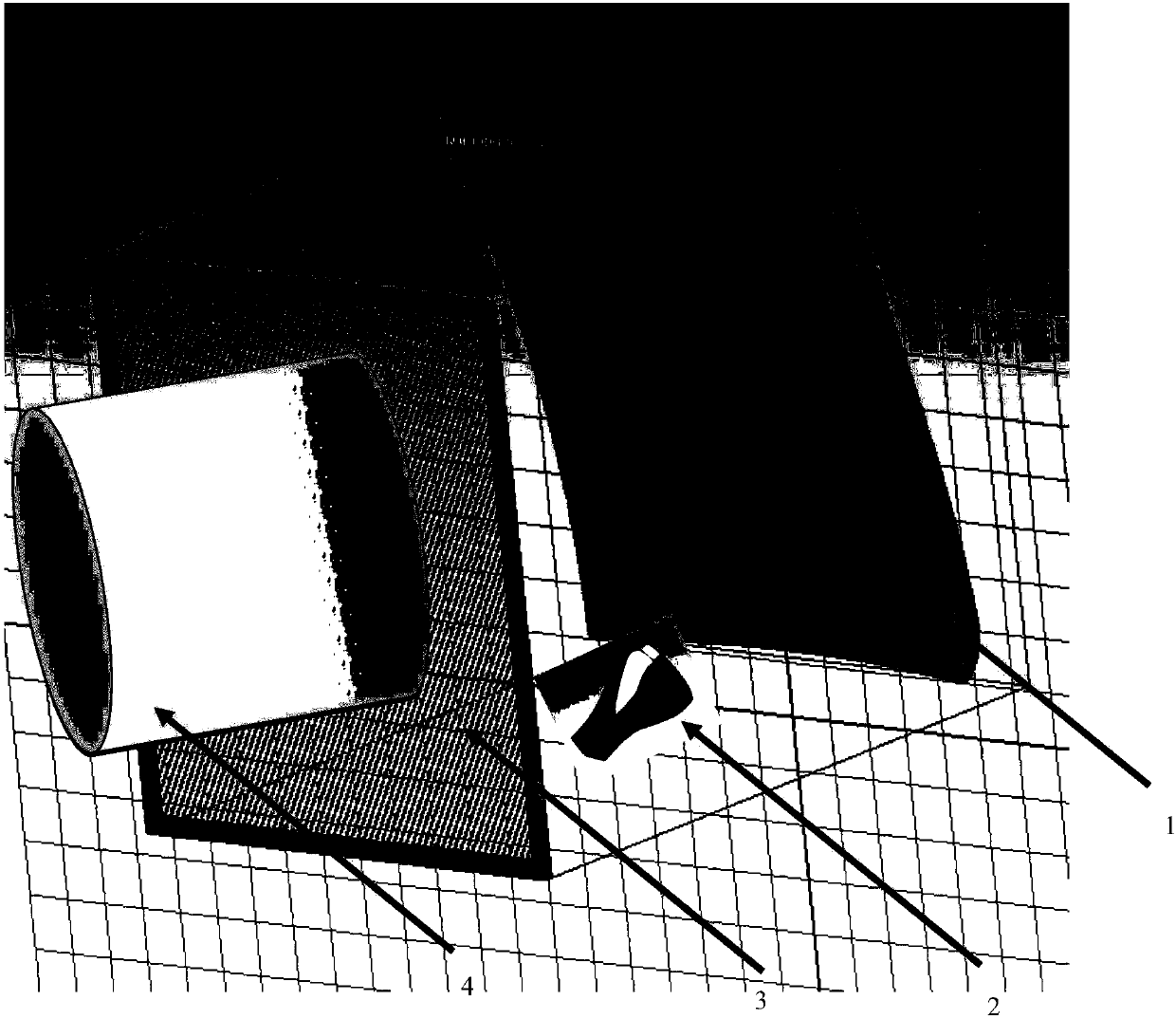
[0033] The invention relates to a high cross polarization isolated single-reflection surface compact field device, the compact field is mainly composed of a reflection surface of the single-reflection surface compact field, a feed source, a polarization grid, a feed source polarization state controller, a polarization grid Polarization state controller. The feed irradiates a precision rotating paraboloid with a single reflector compact field, and collimates the spherical wavefront into a plane wave. A polarization grid is arranged in front of the plane wave quiet zone of the single-reflector compact field, and polarization filtering or gating is performed on the quiet zone field, wherein the polarization states of the feed source and the polarization grid are controlled by respective controllers. The single reflector compact field device of th...


PUM


Abstract

The invention discloses a single reflecting surface compact range device of high cross polarization isolation. The device is mainly composed of a reflecting surface of a single reflecting surface compact range, a feed source and a polarization grid. The feed source illuminates the precise reflecting surface of the single reflecting surface compact range and beforehand collimates and corrects spherical waves into planar waves. To lower shielding of the feed source, an offset feed structure is adopted in geometric layout, while the offset feed layout is the main reason of large cross polarization. The polarization grid is arranged in front of a planar wave silent area of the single reflecting surface compact range, and a silent area range is subjected to polarization filtering and gating, wherein the polarization states of the feed source and the polarization grid are controlled by respective controllers. Polarization and gating of the polarization grid have the advantages of wideband working, can almost completely reflect the polarization component parallel to polarization grid silk, almost completely transmit the polarization component perpendicular to the polarization grid silk and improve the polarization isolation of the single reflecting surface compact range to a great extent with the cost of introducing very small insertion loss. The engineering achievability of compact range system design is improved, and control over the dynamic range of a radio frequency system is improved.

Description

technical field [0001] The present invention relates to the technical field of a single-reflector compact field device, in particular to a single-reflector compact field with high cross-polarization isolation, which is mainly used to improve the polarization isolation of a single-reflector compact field and improve orthogonal polarization It isolates the measurement accuracy of the antenna, and reduces the design and manufacturing difficulty of the compact field system, and is especially suitable for the precision test field of the THz band antenna. Background technique [0002] With the development of THz technology, the demand for large-aperture antennas for precise measurement of THz is increasingly urgent, especially for satellite communication and fully polarized remote sensing antennas, which have high requirements for cross-polarization isolation. The traditional compact field with high cross-polarization isolation usually adopts the equivalent telephoto or large foca...

Claims


Application Information

Patent Timeline
Patent Type & Authority Applications(China)
IPC IPC(8): G01R29/10
CPCG01R29/10
Inventor 李志平霍鹏武建华王正鹏
Owner BEIHANG UNIV
Learn More