
Single-accelerometer-based disturbance observation compensation control method of fast steering mirror

An accelerometer and disturbance observation technology, applied in adaptive control, general control system, control/regulation system, etc., can solve the problems of high price and power consumption, large volume and quality of fiber optic gyroscope, achieve light weight and improve disturbance suppression capacity, small size effect

Active Publication Date: 2018-02-23
INST OF OPTICS & ELECTRONICS - CHINESE ACAD OF SCI
View PDF11 Cites 17 Cited by
  • Summary
  • Abstract
  • Description
  • Claims
  • Application Information

AI Technical Summary

Problems solved by technology

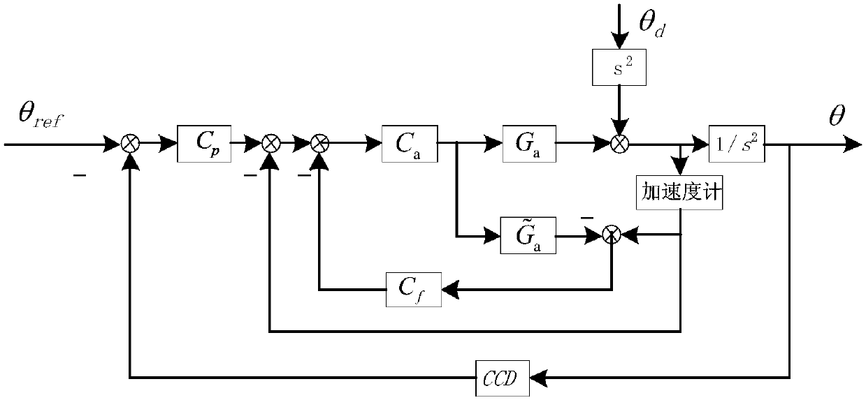
[0003] Aiming at the problems of large volume and mass, high price and high power consumption of the fiber optic gyroscope commonly used in the current fast mirror control system, this paper proposes to replace the fiber optic gyroscope with a small volume, mass, low power consumption and cheap accelerometer to build a closed loop of acceleration and position. Then add a disturbance observation compensator in the acceleration inner loop, observe the external disturbance torque, and feed forward to the given acceleration controller to compensate the influence of the disturbance torque

Method used


Image

  • Single-accelerometer-based disturbance observation compensation control method of fast steering mirror
  • Single-accelerometer-based disturbance observation compensation control method of fast steering mirror
  • Single-accelerometer-based disturbance observation compensation control method of fast steering mirror

Examples


Embodiment Construction

[0026] The specific implementation manners of the present invention will be described in detail below in conjunction with the accompanying drawings.

[0027] as attached figure 1 Shown is a control block diagram of a single accelerometer-based disturbance observation compensation control method for a fast mirror, which includes a disturbance observer compensator loop, an acceleration loop, and a CCD position loop; the feedforward control of the disturbance observation compensator and the acceleration The combination of position feedback control can give full play to the performance of the accelerometer and further improve the disturbance suppression ability of the system. The concrete implementation steps of adopting described device to realize feed-forward control method are as follows:

[0028] Step (1): Accelerometers are respectively installed on the two deflection axes of the fast mirror stabilized platform to respectively sense the angular acceleration of the two axes o...


PUM


Abstract

The invention discloses a single-accelerometer-based disturbance observation compensation control method of a fast steering mirror. In the prior art, the fiber-optic gyroscope employed by the fast steering mirror commonly has disadvantages of large size, high mass, high price, and high power consumption; and the inner-ring intermediate-low-frequency disturbance suppression capability of the exiting accelerometer is low because of low-frequency noises and the fiber-optic gyroscope can not be replaced. With the single-accelerometer-based disturbance observation compensation control method, the above-mentioned problems can be solved. According to the method, on the basis of acceleration feedback, a disturbance observer is added into an acceleration inner ring for feedforward processing; and the disturbance torque from the outside on the platform is observed and the is fed forward to an acceleration controller, thereby realizing disturbance compensation, enhancing the capability of the accelerometer, and improving the intermediate-low-frequency disturbance suppression capability in the system. The system is optimized in terms of sensor usage mode; the capability of the accelerometer sensor is utilized fully based on combination of feedback and feedforward; characteristics of large bandwidth, small size, low mass, and low price of the accelerometer are exploited; and the space and cost are saved.

Description

technical field [0001] The invention belongs to the field of inertial stability control of a photoelectric tracking platform, and in particular relates to a single accelerometer-based fast mirror disturbance observation compensation control method, which mainly improves the low-frequency disturbance suppression ability of the system, thereby further improving the stability of the visual axis of the photoelectric tracking equipment of the motion platform performance. Background technique [0002] In the photoelectric tracking system, compared with the coarse tracking rack, the fast mirror has a small inertia and a high bandwidth, so it is widely used in the fine tracking system. The fast mirror on the moving platform is not only used to track the target, but also to suppress the disturbance of the moving platform, and the medium and high frequency disturbance suppression of the whole system mainly depends on the suppression ability of the fast mirror. In terms of control met...

Claims


Application Information

Patent Timeline
IPC IPC(8): G05B13/04
CPCG05B13/042
Inventor 罗勇黄永梅邓超毛耀吴琼雁
Owner INST OF OPTICS & ELECTRONICS - CHINESE ACAD OF SCI
Learn More