High-power optical fiber laser

A fiber laser, high-power technology, applied in the direction of lasers, laser components, phonon exciters, etc., can solve problems such as Raman scattering, multi-mode oscillation, pump source chip interference, etc., to reduce nonlinear effects and improve life , to avoid the effect of mutual damage

Pending Publication Date: 2018-02-23
SHANDONG UNIV +1
View PDF10 Cites 20 Cited by
  • Summary
  • Abstract
  • Description
  • Claims
  • Application Information

AI Technical Summary

Problems solved by technology

The first type of unidirectionally pumped fiber laser cavity structure has high pump power in the front part of the active fiber in the cavity, severe stimulated spontaneous emission, and high temperature, which easily lead to fiber nonlinear effects, resulting in Kerr effect and affected Stimulated Raman scattering, even multi-mode oscillation, affects the stability of the laser
The second bidirectionally pumped fiber laser cavity structure has significantly improved pump light power distribution and temperature uniformity on the active fiber in the cavity compared with the first one. Due to the limited absorption of the pump light, there is some residual pump light in the forward and reverse transmission of the pump light in the inner cladding, and these residual pump lights will be combined by the forward pump signal combiner and the reverse pump signal The laser is transmitted to the pump fiber and enters the pump source, thereby causing interference and damage to the pump source chip, affecting the life of the pump source and the stability of the fiber laser
The third type of fiber laser with MOPA structure is divided into two stages, its circuit control and optical path structure are more complex than the first two, and its cost, beam quality and working stability are inferior to single-cavity fiber lasers in the pulse working state.
This structure does not use a reverse pump light source, but only sends back the very low-power forward residual pump light in reverse, which cannot significantly increase the output power of the laser.

Method used


Image

  • High-power optical fiber laser

Examples


Embodiment Construction

[0024] In order to understand the technical content of the present invention more clearly, the following examples are given in detail, the purpose of which is only to better understand the content of the present invention but not to limit the protection scope of the present invention.

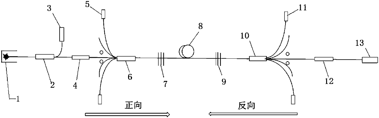
[0025] Such as figure 1 As shown, a high-power fiber laser, the cavity of the fiber laser includes a forward pump pump source module, a forward pump / signal combiner 6, a high reflection grating 7, a doped fiber 8, and a low reflection output grating 9 , a reverse pump / signal combiner 10 and a reverse pump pump source module; the doped fiber is a double-clad or triple-clad active fiber;

[0026] The forward pumping pump source module includes a plurality of forward pumping lasers 5, and the forward pumping lasers 5 provide pumping light to be transmitted to the forward pumping / signal beam combiner 6 through the confluence of pumping optical fibers of the forward pumping / signal beam combiner 6. ...


PUM


Abstract

The invention discloses a high-power optical fiber laser. The laser structurally comprises a residual light collector, a red light / signal light beam combiner, a red light laser, a reverse cladding light mode stripper, a forward pumping pump source module, a forward pumping / signal beam combiner, a high-reflection grating, doped optical fiber, a low-reflection output grating, a reverse pumping / signal beam combiner, a reverse pumping pump source module, a forward cladding light stripper, and output optical fiber with an antireflection film end cap. Based on a linear fabry-perot resonance cavity structure, the forward pumping pump source module and the reverse pumping pump source module, with different wavelengths, provided with narrow-band protection filters are adopted, the forward pumping / signal beam combiner and the reverse pumping / signal beam combiner pump doped optical fiber from the front end and the back end of the doped optical fiber through the high-reflection grating and the low-reflection output grating at the same time, so that multi-kilowatt-class power stable output of the optical fiber laser is achieved, and mutual damage of residual pumping light on two sides to a pumpsource chip is avoided.

Description

technical field [0001] The invention relates to the field of fiber lasers, in particular to a bidirectionally pumped high-power fiber laser. Background technique [0002] In recent years, kilowatt-class ytterbium-doped single-mode fiber lasers based on all-fiber structures have shown good application prospects in the industrial and military fields due to their high electro-optical efficiency, good beam quality, and stability and reliability, and have been widely used in general Cutting, welding, surface treatment and 3D printing of metals such as steel and high anti-metals such as aluminum and copper. [0003] Most kilowatt-class fiber lasers with an all-fiber structure adopt the following three laser resonator structures: 1) single-fiber FAP cavity pumped in one direction by multiple identical pump sources through a forward-pumped beam combiner; 2) through two The pump beam combiner, in which the reverse pump / signal beam combiner is a side pump structure, adopts multiple i...

Claims


Application Information

Patent Timeline
Patent Type & Authority Applications(China)
IPC IPC(8): H01S3/067H01S3/094H01S3/08
CPCH01S3/06733H01S3/06795H01S3/08013H01S3/094011H01S3/094096H01S3/0675
Inventor 卓壮
Owner SHANDONG UNIV
Why Eureka
Try Eureka