Specific harmonic cancellation multi-level radio frequency pulse width modulation method and modulator

A specific harmonic elimination and pulse width modulation technology, which is applied in the direction of pulse duration/width modulation, etc., can solve the problems of complex tuning filter design, restricting DTx wide-band performance, and spurs

Active Publication Date: 2018-02-23
中国人民解放军国防科技大学第六十三研究所
View PDF12 Cites 8 Cited by
  • Summary
  • Abstract
  • Description
  • Claims
  • Application Information

AI Technical Summary

Problems solved by technology

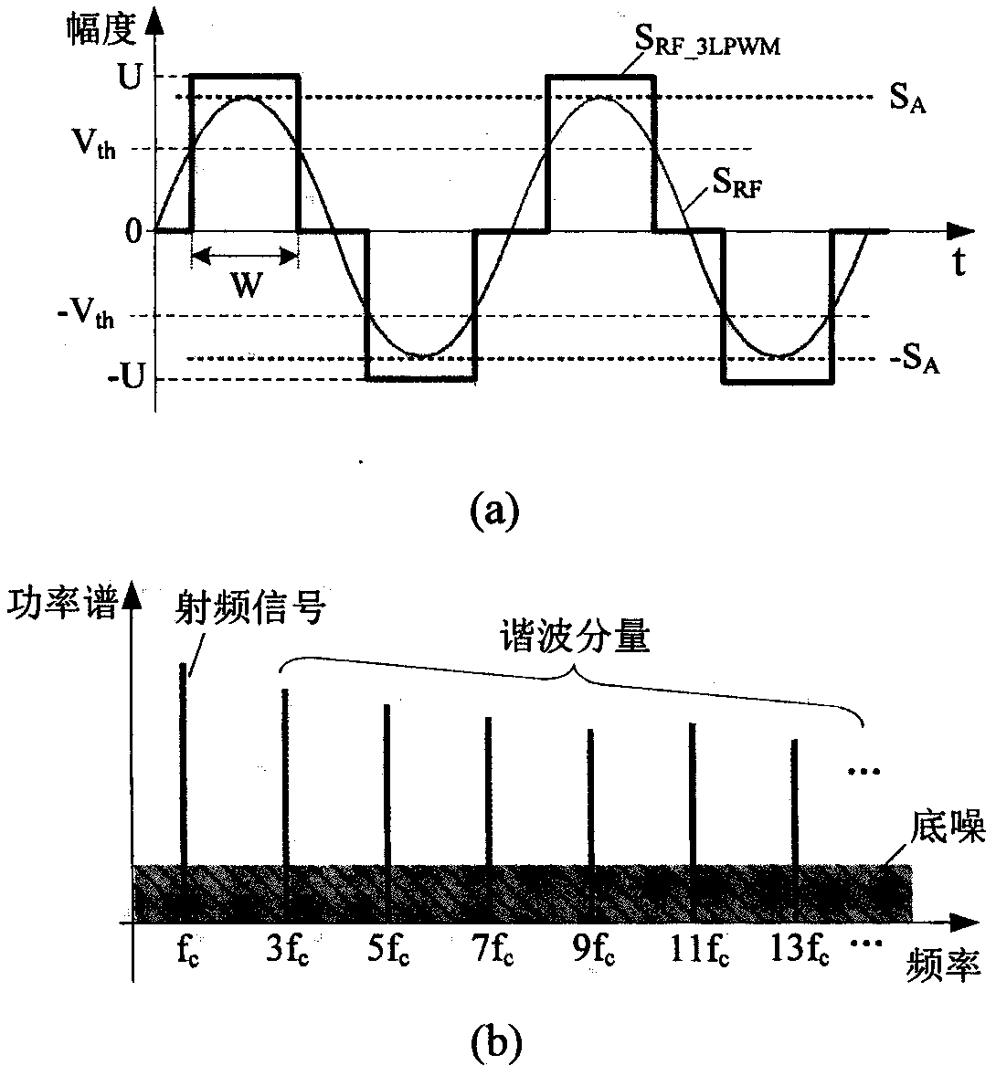
[0026] In the prior art, for DTx applications, it is necessary to implement RF-PWM in the digital domain. Due to the discrete characteristics of time and amplitude of digital signals, whether it is 3-level or M-level RF-PWM, its modulation performance and sampling The minimum time resolution (that is, the minimum discrete time interval) is directly related to the time, and is limited by the physical realization of RF-PWM. Its limited minimum time resolution will bring nonlinear distortions such as spurs, intermodulation and noise floor. In order to improve The performance of the existing technology RF-PWM, high-performance digital delay line (DDL) technology based on semiconductor technology is widely used [P.A.J.Nuyts, et al., "A fully digitaldelay line based GHz range multimode transmitter front-end in 65- nm CMOS,” IEEE J. Solid-State Circuits, vol.47, no.7, pp.1681-1692, 2012; P.A.J. Nuyts, et al. “A fully digital PWM-based 1 to 3GHz multistandard transmitter in 40-nmCMOS , "in 2013 IEEE Radio Frequency Integrated

Method used


Image

  • Specific harmonic cancellation multi-level radio frequency pulse width modulation method and modulator
  • Specific harmonic cancellation multi-level radio frequency pulse width modulation method and modulator
  • Specific harmonic cancellation multi-level radio frequency pulse width modulation method and modulator

Examples


Example Embodiment

[0085] In the following, the present invention will be further described in detail in conjunction with specific embodiments and drawings. The exemplary embodiments of the present invention and the description thereof are suitable for helping to understand the innovative solutions of the present invention, and should not be understood as unnecessary limitations on the protection scope of the present invention.

[0086] For the purpose of brevity and to avoid unnecessary details from obstructing the description of the invention, multiple steps, parts or aspects of the radio frequency pulse width modulation method and modulator are omitted, and only the description and display in this text are essential for understanding the content of the invention. Those steps, methods, elements, or devices that are necessary or related, and detailed descriptions of the steps, methods, elements, or devices are omitted.

[0087] In an embodiment of the present invention, let K=1, N=2, and M=5, then f...


PUM


Abstract

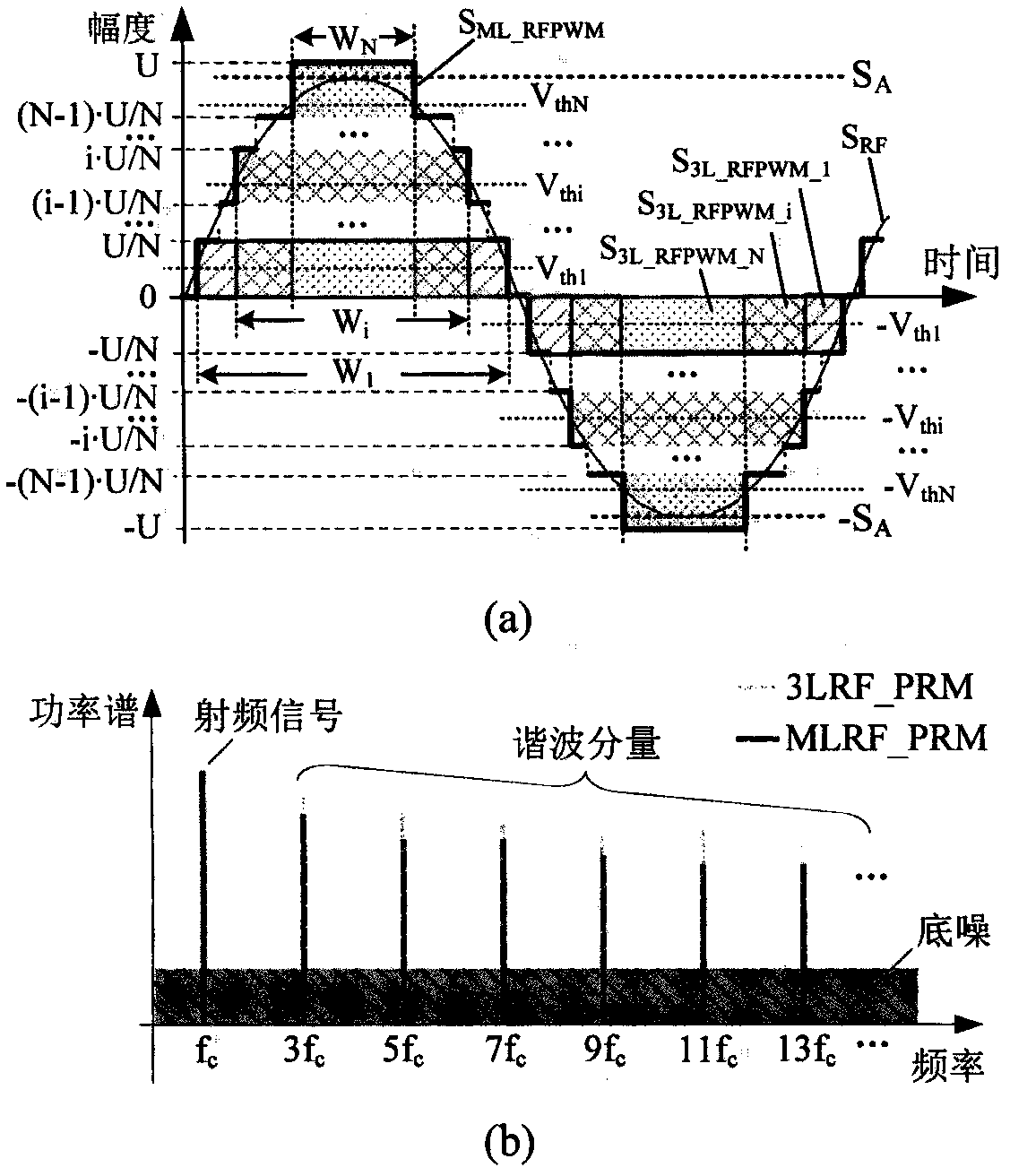
The invention discloses a specific harmonic cancellation multi-level radio frequency pulse width modulation method in which K odd number of specific harmonic waves are selected, and M-level RF-PWM signals are processed to be equivalent to N 3-level RF-PWM signals with pulse width separately controlled by corresponding comparison thresholds and stacked in a weighted manner, wherein K, M and N are all integers more than 0, N is more than K, and M is equal to 2N+1; N comparison thresholds and corresponding weighting coefficients are controlled in real time according to a normalized envelope signal SA, so that the K specific harmonic wave components of the N 3-level RF-PWM signals has stacked in a weighted manner are mutually counteracted, a base wave component is in direct proportion to the SA, and thus the K specific harmonic waves and integer multiples of odd harmonic waves of the M-level RF-PWM signals are eliminated. Based on the method, the invention also provides a specific harmoniccancellation multi-level radio frequency pulse width modulator. Compared with the prior art, the modulation method and the modulator have the beneficial effects that on the basis that the basic modulation performance is equivalent to the RF-PWM of the same level in the prior art, the suppression requirement on the filter is effectively reduced, the cost and size of the filter are reduced, and thus the comprehensive performance of the wide frequency band DTX is improved.

Description

technical field [0001] The invention relates to the field of wireless communication, in particular to a specific harmonic elimination multilevel radio frequency pulse width modulation method and modulator. Background technique [0002] The transmitter is one of the important components of the wireless communication system. Its role is to up-convert the modulated baseband signal to radio frequency (RF), and amplify the radio frequency signal to a power level sufficient for antenna transmission. It is the main factor that determines the output signal quality and work efficiency of the wireless communication system. Smaller size, lower power consumption, higher communication rate, digitization and reconfigurability are the development direction of the transmitter. In recent years, the high-efficiency, wide-band digital transmitter (DTx) technology combined with direct digital radio frequency modulation (DDRFM), switched mode power amplifier (SMPA) and tuned filter has develope...

Claims


Application Information

Patent Timeline
IPC IPC(8): H03K7/08
CPCH03K7/08
Inventor 周强姚富强魏志虎
Owner 中国人民解放军国防科技大学第六十三研究所
Why Eureka
Try Eureka