Novel multi-shank polishing machine

A technology for grinding and polishing machines and tool handles, applied in grinding/polishing equipment, grinders, abrasive belt grinders, etc., can solve the problems that the friction force cannot be guaranteed to be the same, the tool handle is prone to offset, and the functional stability is poor. Consistent wrap angle, less shank offset, and consistent effect

Pending Publication Date: 2018-03-02
DONGGUAN EZAT AUTOMATION TECH
View PDF0 Cites 2 Cited by
  • Summary
  • Abstract
  • Description
  • Claims
  • Application Information

AI Technical Summary

Problems solved by technology

[0005] The disadvantage is that the contact between the abrasive belt of this structure and the tool handle is a line contact, resulting in a small grinding area and low efficiency; when the abrasive belt polishes multiple tool handles at the same time, the abrasive belt cannot guarantee that each tool handle will be produced. The friction force is the same; in addition, the spindle box adjusts the angle of the tool clamping table through the rack and pinion mechanism, thereby adjusting the angle of the handle. This rack and pinion mechanism locks the handle so that the abrasive belt polishes the handle. The locking function of the rack is poor in stability, and the handle is prone to shift during the polishing process of the handle, resulting in low polishing accuracy

Method used


Image

  • Novel multi-shank polishing machine
  • Novel multi-shank polishing machine
  • Novel multi-shank polishing machine

Examples


Embodiment Construction

[0022] Below in conjunction with accompanying drawing and specific embodiment the present invention is described in further detail:

[0023] The directional terms mentioned in the following embodiments, such as "up, down, left, right, X direction, Y direction, Z direction" are only referring to the directions of the accompanying drawings. Therefore, the directional terms used are for illustration and not for to limit the invention.

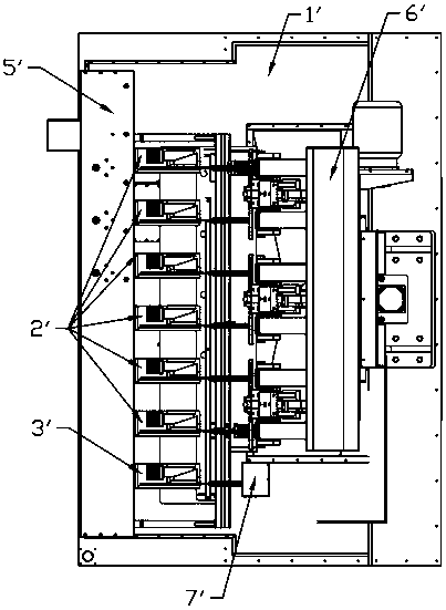
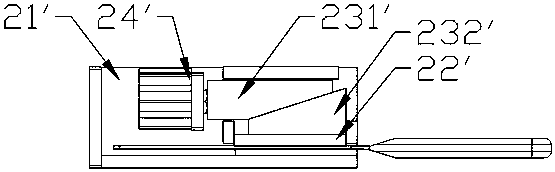
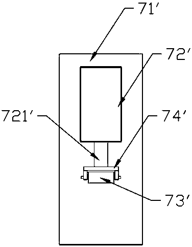
[0024] Figure 4As shown, the present invention provides a novel multi-shank grinding and polishing machine, including a control system, a machine base 1, six tool clamping platforms 2, a tool mold clamping platform 3, a two-dimensional electric displacement platform 4, and driving the six The headstock 5 that the three tool clamping platforms rotate at the same time, the abrasive belt grinding mechanism 6 that polishes the tool handles on the six tool clamping platforms simultaneously, and the profiling device 7, the abrasive belt grinding mecha...


PUM


Abstract

The invention provides a novel multi-shank polishing machine. The novel multi-shank polishing machine comprises a control system, a stand, multiple cutter clamping tables, a main shaft box, a two-dimensional electric displacement platform and an abrasive belt polishing mechanism; the abrasive belt polishing mechanism comprises an abrasive belt wheel bracket fixed on the stand, a driving abrasive belt wheel fixed on the abrasive belt wheel bracket, a driving abrasive belt wheel driver fixed on the abrasive belt wheel bracket, a driven abrasive belt wheel fixed on the abrasive belt wheel bracket, an abrasive belt matched with the driving abrasive belt wheel and the driven abrasive belt wheel, and multiple supercharging wheels for increasing friction force of the abrasive belt to shanks; themultiple cutter clamping tables are positioned between the driving abrasive belt wheel and the driven abrasive belt wheel; and the multiple supercharging wheels are positioned between the driving abrasive belt wheel and the driven abrasive belt wheel. Compared with the prior art, the contact between the abrasive belt and the shanks is changed from line contact to surface contact, so that the polishing efficiency is greatly improved; and the supercharging wheels enable the abrasive wheel to achieve consistent polishing effects on each shank.

Description

technical field [0001] The invention relates to a novel multi-handle grinding and polishing machine. Background technique [0002] In order to improve the grinding efficiency of handles, Chinese Patent No. (2017203501913) discloses a multi-handle polishing machine, such as Figure 1 to Figure 3 As shown, a multi-handle polishing machine includes a control system, a machine base 1', and several tool clamping tables 2' for clamping tools that can move in the XY direction and rotate around the Y direction, and are used for clamping The tool mold mounting platform 3', which can move along the XY direction and rotate around the Y direction, is electrically connected to the control system and is used to adjust the tool clamping platform 2' and the tool mold mounting in the XY direction. The two-dimensional electric displacement platform 4' at the position of the clamping table 3', the spindle box 5' used to drive the tool clamping table and the tool mold clamping table to rotate a...

Claims


Application Information

Patent Timeline
IPC IPC(8): B24B21/00
CPCB24B21/008
Inventor 蓝海锋李俊华傅卫玲刘胜勇邓志勇
Owner DONGGUAN EZAT AUTOMATION TECH
Why Eureka
Try Eureka