A detachable flexible support assembly

A flexible support and support technology, applied in the field of optical remote sensing, can solve the problems of low support rigidity, complex support structure, limited support rigidity, etc., and achieve the effect of reducing centrifugal deformation of mirror surface, strong environmental adaptability, and improving structural rigidity

Active Publication Date: 2019-03-29
CHANGCHUN INST OF OPTICS FINE MECHANICS & PHYSICS CHINESE ACAD OF SCI
View PDF7 Cites 0 Cited by
  • Summary
  • Abstract
  • Description
  • Claims
  • Application Information

AI Technical Summary

Problems solved by technology

However, the flexible support structure of the reflector has the following disadvantages: a) the integrated design of the flexible support and the mirror body, the centrifugal deformation of the mirror surface is likely to occur due to the existence of the flexible link in the process of mirror mirror surface processing, so it is only suitable for the support design of small and medium-diameter reflectors; b) The flexible support structure and the mirror body are designed in an integrated manner, and the flexible groove of the flexible support structure is difficult to process; c) The back of the mirror and the support structure interfere with each other, which is not conducive to achieving a higher lightweight rate; d) The mirror The support stiffness of the flexible support structure is limited, which is only suitable for small and medium aperture optical systems
This structure is mostly used in the flexible support structure of super-large-diameter non-metallic reflectors, and has the following disadvantages: 1. The support structure is complex, including reflectors, flexible joints, taper sleeves, and multiple installation links; 2. The process is complicated and the reflection The mirror and the tapered sleeve are fixed by glue bonding. During the bonding process, the stability of the mirror surface shape needs to be monitored. If the bonding fails, it will take a lot of time to clean the foam and the cycle will be longer.
This support structure suitable for small-aperture mirrors has low support rigidity, and there is a problem of uncontrollable deformation of adhesive parts. This solution is similar to Document 2, except that it contains a kinematic adjustment mechanism to adjust the angle of the mirror.

Method used


Image

  • A detachable flexible support assembly
  • A detachable flexible support assembly
  • A detachable flexible support assembly

Examples


Embodiment Construction

[0028]In order to enable those skilled in the art to better understand the solutions of the present invention, the following will clearly and completely describe the technical solutions in the embodiments of the present invention in conjunction with the drawings in the embodiments of the present invention. Obviously, the described embodiments are only It is an embodiment of a part of the present invention, but not all embodiments. Based on the embodiments of the present invention, all other embodiments obtained by persons of ordinary skill in the art without making creative efforts shall fall within the protection scope of the present invention.

[0029] The terms "first", "second", "third", "fourth", etc. (if any) in the description and claims of the present invention and the above drawings are used to distinguish similar objects, and not necessarily Used to describe a specific sequence or sequence. It is to be understood that the terms so used are interchangeable under appr...


PUM


Abstract

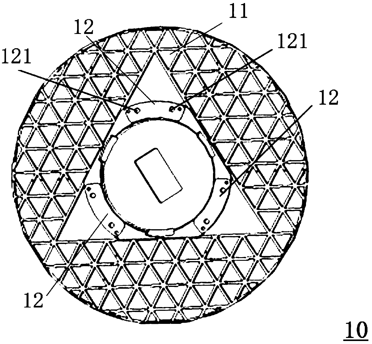
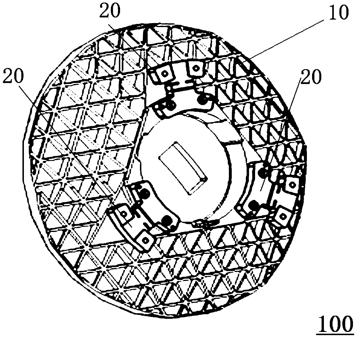
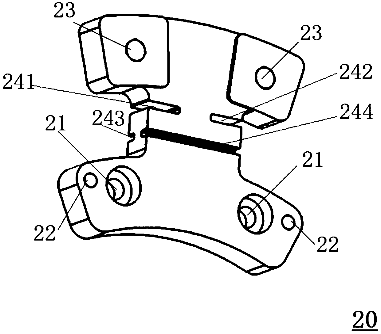
The invention provides a detachable flexible support device, comprising a reflector, the mirror body of which is provided with a circumferential flange surface; and at least three flexible supports, each of which is connected to the reflector And uniformly distributed on the circumferential flange surface, each flexible supporting member is provided with a counterbore, a pin hole, a threaded hole and at least one pair of staggered and orthogonal flexible grooves. A detachable flexible support structure that can not only reduce the difficulty of flexible processing, but also improve the light weight of the mirror.

Description

technical field [0001] The invention relates to the field of optical remote sensing technology, in particular to a detachable flexible support assembly. Background technique [0002] The development trend of space optical remote sensor optical system is high light weight rate, light and small size, high resolution, high integration and high cost performance. High-precision mirrors are of great significance for aerospace payloads. The optical system can obtain high-definition photos in fields such as ground reconnaissance, remote sensing, and detection, and can be widely used in civilian, military, and national defense fields. With the development of single-point diamond turning technology (SPDT), metal-based mirrors are successfully used in optical imaging systems with the advantages of rapid and low-cost manufacturing. [0003] Metal reflectors are cost-effective and have good machinability. They can be directly drilled or tapped on the reflector. It is easy to realize th...

Claims


Application Information

Patent Timeline
Patent Type & Authority Patents(China)
IPC IPC(8): G02B7/183G02B7/192
CPCG02B7/183
Inventor 张继真张新王灵杰谭双龙谢晓麟
Owner CHANGCHUN INST OF OPTICS FINE MECHANICS & PHYSICS CHINESE ACAD OF SCI
Why Eureka
Try Eureka