Recovery of styrene from pyrolysis gasoline by extractive distillation
A technology of styrene and distillation column, applied in azeotropic/extractive distillation, distillation separation, extraction purification/separation, etc., can solve problems such as difficult component separation
- Summary
- Abstract
- Description
- Claims
- Application Information
AI Technical Summary
Problems solved by technology
Method used
Image
Examples
Embodiment I
[0036] This example illustrates the application of various solvents in the extractive distillation of pyrolysis gasoline feedstock.
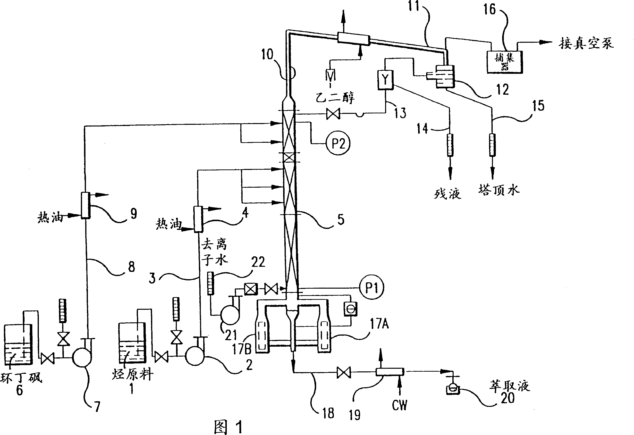
[0037] Containing 35.3% toluene, 4.3% vinyl norbornene, 11.8% ethylbenzene, 3.3% p-xylene, 0.2% 2,5-diethylthiophene, 5.5% o-xylene, 0.5% dicyclopentadiene , 27.9% styrene, 0.1% styrene propylene, and 0.3% 6,6-dimethylfulvene (by weight) were added to a pyrolysis gasoline feedstock at various solvent:feed ratios with an extraction solvent. The whole mixture (including the extraction solvent) is heated under reflux conditions for 20-60 minutes in a gas-liquid equilibrium still with one theoretical stage and equipped with a total reflux condenser. Samples of the pyrolysis gasoline feedstock and equilibrium vapor were taken prior to solvent addition. Solvent was fed to the still pot at solvent:feed ratios of 1:1 and 5:1. After equilibrium is reached, a small sample of the condensed vapor is taken using the septum located in the lower part of the ...
Embodiment II
[0045] This embodiment illustrates that sulfolane is used as an extractant to carry out extractive distillation of the raw material mixture described in Example 1. The distillation apparatus was the same as described in Example 1. For this experiment, 75 g of pyrolysis gasoline feedstock was added to a vapor-liquid equilibrium still, and feedstock and vapor samples were taken for analysis. Solvent was fed to the kettle at solvent:feed ratios of 1:1 (75 grams added) and 5:1 (375 grams added). After equilibrium is reached, a small sample of the condensed vapor is taken using the septum located in the lower part of the total reflux condenser. The sample was analyzed by gas chromatography and the weight fraction of the feedstock components in the gas phase was determined. The test results are summarized in Table II.
[0046] Table II Component A / B Relative Volatility A / B Relative Volatility A / B Relative Volatility Description No solvent 1:1 solvent 1 ...
Embodiment III
[0050] This example illustrates the use of 2-pyrrolidinedione as an extractant for extractive distillation of the raw material mixture described in Example I. The distillation apparatus was the same as described in Example 1. For this experiment, 75 g of pyrolysis gasoline feedstock was added to a vapor-liquid equilibrium still, and feedstock and vapor samples were taken for analysis. Solvent was fed to the kettle at solvent:feed ratios of 1:1 (75 grams added) and 5:1 (375 grams added). After equilibrium is reached, a small sample of the condensed vapor is taken using the septum located in the lower part of the total reflux condenser. The sample was analyzed by gas chromatography and the weight fraction of the feedstock components in the gas phase was determined. The test results are summarized in Table III.
[0051] Table III Component A / B Relative Volatility A / B Relative Volatility A / B Relative Volatility Description No solvent 1:1 solvent 1 : ...
PUM
 Abstract
Description
Claims
Application Information
 - R&D
- Intellectual Property
- Life Sciences
- Materials
- Tech Scout
- Unparalleled Data Quality
- Higher Quality Content
- 60% Fewer Hallucinations
Browse by: Latest US Patents, China's latest patents, Technical Efficacy Thesaurus, Application Domain, Technology Topic, Popular Technical Reports.
© 2025 PatSnap. All rights reserved.Legal|Privacy policy|Modern Slavery Act Transparency Statement|Sitemap|About US| Contact US: help@patsnap.com


