Deburring device for turboshaft

A technology of deburring and deburring mechanism, applied in metal processing equipment, grinding/polishing equipment, grinding machines, etc., can solve the problems of inability to meet automation equipment, affect product quality, low work efficiency, etc., to meet automation equipment and equipment. Maintenance, improve deburring effect, improve work efficiency effect

Pending Publication Date: 2018-03-06
BORGWARNER AUTOMOTIVE COMPONENTS (JIANGSU) CO LTD
View PDF1 Cites 3 Cited by
  • Summary
  • Abstract
  • Description
  • Claims
  • Application Information

AI Technical Summary

Problems solved by technology

There are more or less burrs in the production process of the turbine impeller and the shaft, especially in the sealing groove area of ​​the blade of the turbine impeller and the shaft, there are many burrs, see Figure 20 , will directly affect the quality of the product, and it is necessary to remove the burrs manually or manually with the deburring mechanism. Due to the complicated structure of the scroll shaft, relying on manual deburring, the labor cost is relatively large and the work efficiency is very low; the existing deburring mechanism The quality of deburring has been slightly improved, but there is still further improvement in its working efficiency. The function of the existing deburring mechanism cannot meet the needs of automation equipment, and its protective structure such as the dust collector needs to be further improved.
[0003] In the process of deburring the scroll shaft by the existing deburring mechanism, a clamping mechanism is required to position the scroll shaft. Patent document CN203918779U discloses a workpiece clamping device for a deburring machine. Although it can realize the clamping and mou

Method used


Image

  • Deburring device for turboshaft
  • Deburring device for turboshaft
  • Deburring device for turboshaft

Examples


Embodiment Construction

[0040] In order to understand the technical content of the present invention more clearly, the following examples are given in detail, the purpose of which is only to better understand the content of the present invention but not to limit the protection scope of the present invention.

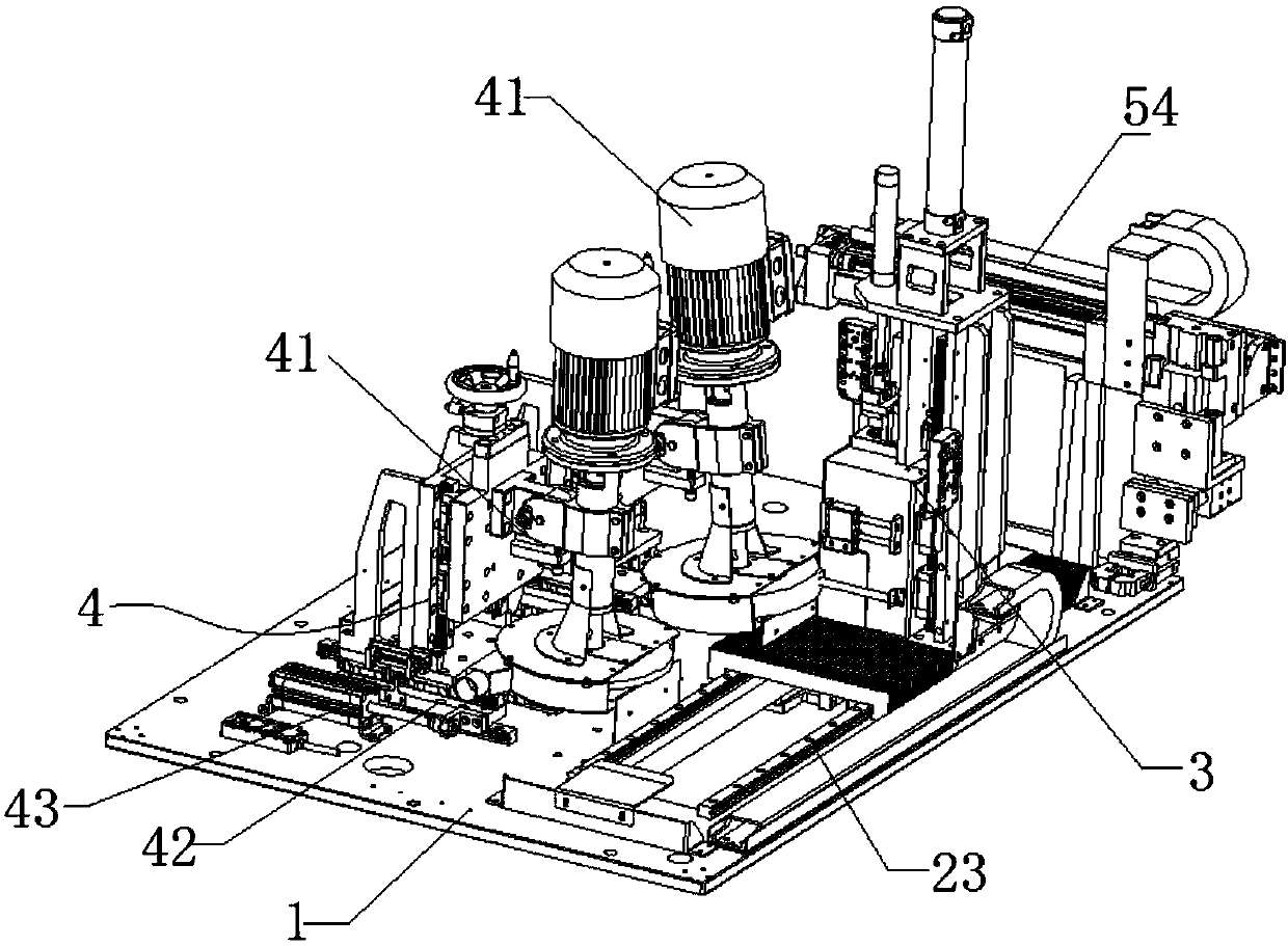
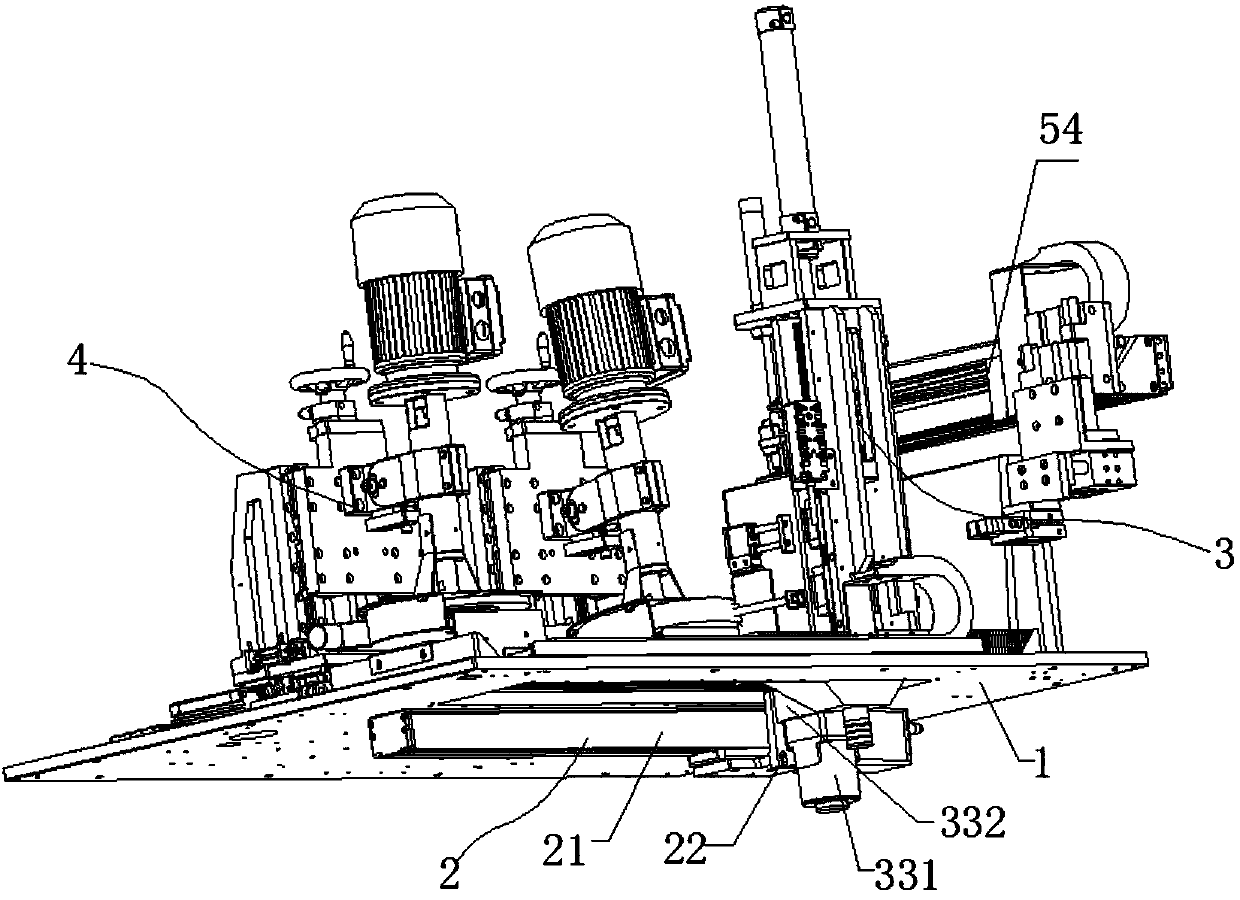
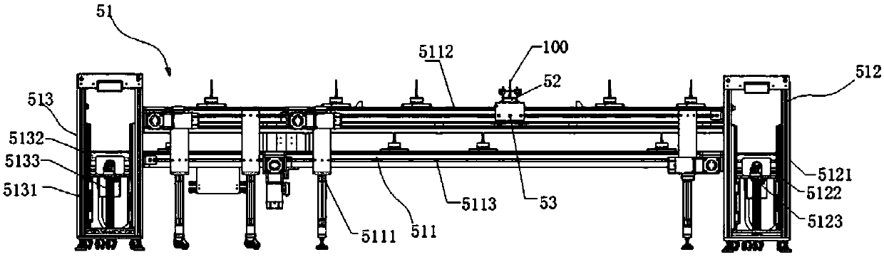
[0041] Such as figure 1 , figure 2 with image 3 Shown, a kind of vortex shaft deburring equipment comprises horizontal working platform 1, is provided with two deburring stations on the horizontal working platform, corresponding to each deburring station, is provided with a deburring mechanism 4 on the horizontal working platform; Adjusting the inclination angle of the brush plate of the deburring mechanism can accurately deburr the blades of the turbine impeller of the vortex shaft and the welded part of the rotating shaft and the turbine impeller; it also includes a clamping mechanism for clamping and positioning the vortex shaft 3, drive The moving positioning mechanism 4 and the automa...


PUM


Abstract

The invention discloses a vortex shaft deburring device, which comprises a horizontal working platform, at least one deburring station is arranged on the horizontal working platform, corresponding to each deburring station, and a deburring mechanism is arranged on the horizontal working platform; It also includes a clamping mechanism for clamping and positioning the scroll shaft, a mobile positioning mechanism for driving the clamping mechanism to move and position between each deburring station, and an automatic loading and unloading mechanism; the invention innovatively designs an automatic loading and unloading mechanism , to realize the automatic loading and unloading function of the vortex shaft; through the improvement of the structure of the clamping mechanism, the clamping, positioning and rotation functions of the vortex shaft are realized, and the burrs can be prevented from splashing out, preventing the burrs from affecting the normal operation of the mechanism, and affecting the surrounding environment and environment. Workers bring harm. Through the improvement of the deburring mechanism, it can better meet the needs of automation equipment and equipment maintenance, thereby greatly improving work efficiency and deburring effect, and is suitable for mass industrial production.

Description

technical field [0001] The invention relates to the technical field of turbochargers, in particular to a turboshaft deburring device. Background technique [0002] As a turbine component, the vortex shaft 100 or turbine shaft is an important part of an automobile turbocharger and consists of a turbine wheel 101 and a shaft 102 . There are more or less burrs in the production process of the turbine impeller and the shaft, especially in the sealing groove area of ​​the blade of the turbine impeller and the shaft, there are many burrs, see Figure 20 , will directly affect the quality of the product, and it is necessary to remove the burrs manually or manually with the deburring mechanism. Due to the complicated structure of the scroll shaft, relying on manual deburring, the labor cost is relatively large and the work efficiency is very low; the existing deburring mechanism The quality of deburring has been slightly improved, but there is still further improvement in its work e...

Claims


Application Information

Patent Timeline
IPC IPC(8): B24B9/04B24B55/06
CPCB24B9/04B24B55/06
Inventor 徐东升高华山张亚南
Owner BORGWARNER AUTOMOTIVE COMPONENTS (JIANGSU) CO LTD
Why Eureka
Try Eureka