Signal interference device and method
A signal interference and signal technology, applied in the field of communication, can solve the problems of high power consumption of equipment, inability to completely block terminal communication, and high power requirements
- Summary
- Abstract
- Description
- Claims
- Application Information
AI Technical Summary
Problems solved by technology
Method used
Image
Examples
Embodiment 1
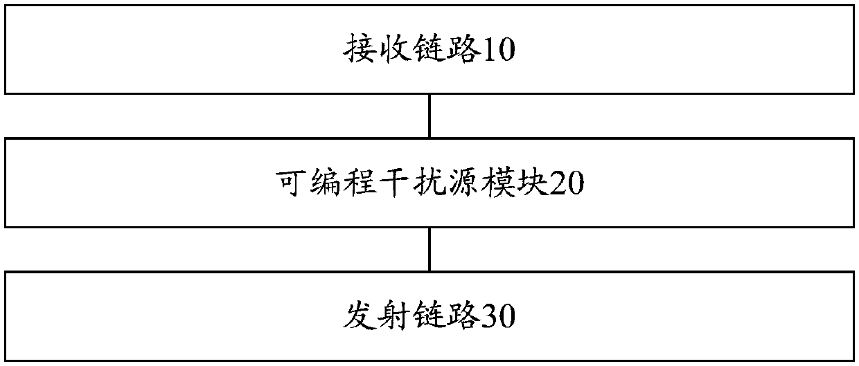
[0067] refer to figure 1 , shows a structural block diagram of a signal interference device in Embodiment 1 of the present invention. In this embodiment, the signal interference device includes:
[0068] The receiving link 10 is configured to receive an air signal, convert the air signal into a digital signal, and send the digital signal to the programmable interference source module.
[0069] In this embodiment, the receiving link 10 may receive the air signal in any appropriate manner, for example, but not limited to, receiving the air signal through an antenna provided in the receiving link 10 . Further, the receiving link 10 can convert the received air signal into a digital signal and send it to the programmable interference source module, so that the programmable interference source module can analyze the air environment according to the digital signal, and determine according to the analysis result Match the transmit modulation signal.
[0070] The programmable inter...
Embodiment 2
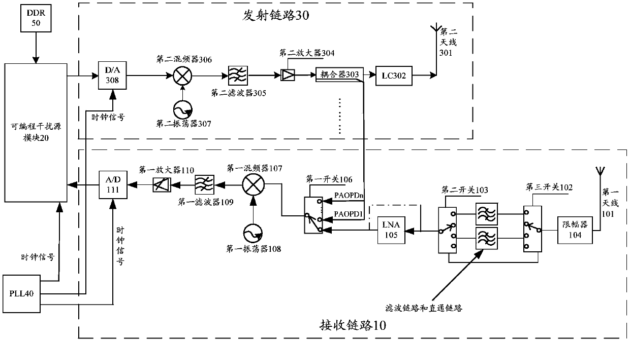
[0077] refer to figure 2 , shows a schematic structural diagram of a signal interference device in Embodiment 2 of the present invention. Such as figure 2 As shown, the signal interference device may include: a receiving link 10 , a programmable interference source module 20 , a transmitting link 30 and a phase locked loop (PLL, Phase Locked Loop) 40 .
[0078] in,
[0079] The receiving chain 10 includes: a first antenna 101, a limiter 104, a third switch 102, at least one filter link and a direct link, a second switch 103, a low noise amplifier (LNA, Low Noise Amplifier) connected in sequence ) 105, a first switch 106, a first mixer 107, a first filter 109, a first amplifier 110 and an analog-to-digital converter (A / D, Analog-to-Digital Converter) 111, and, with the first A mixer 107 is connected to a first oscillator 108 .
[0080] The transmission chain 30 includes: a digital-to-analog converter (D / A, Digital-to-AnalogConverter) 308, a second mixer 306, a second fi...
Embodiment 3
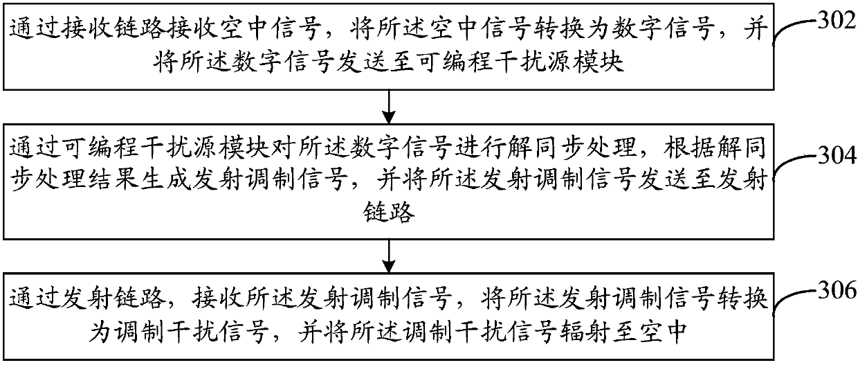
[0100] Based on the same inventive concept as the above device embodiment, refer to image 3 , shows a flow chart of steps of a signal interference method in Embodiment 3 of the present invention. In this embodiment, the signal interference method includes:
[0101] Step 302: Receive an air signal through a receiving link, convert the air signal into a digital signal, and send the digital signal to a programmable interference source module.
[0102] Step 304: Perform desynchronization processing on the digital signal through the programmable interference source module, generate a transmission modulation signal according to the desynchronization processing result, and send the transmission modulation signal to a transmission link.
[0103] Step 306: Receive the transmit modulation signal through a transmit link, convert the transmit modulated signal into a modulated interference signal, and radiate the modulated interference signal into the air.
[0104] It can be seen that i...
PUM
 Abstract
Description
Claims
Application Information
 - R&D
- Intellectual Property
- Life Sciences
- Materials
- Tech Scout
- Unparalleled Data Quality
- Higher Quality Content
- 60% Fewer Hallucinations
Browse by: Latest US Patents, China's latest patents, Technical Efficacy Thesaurus, Application Domain, Technology Topic, Popular Technical Reports.
© 2025 PatSnap. All rights reserved.Legal|Privacy policy|Modern Slavery Act Transparency Statement|Sitemap|About US| Contact US: help@patsnap.com


