Vertical adjustable cable pay-off rack

A pay-off frame and cable technology, which is applied to the installation of cables, cable installation devices, electrical components, etc., can solve the problems of confusion at the pay-off site, dead knots, inconvenient pay-out, etc., and achieve a reasonable internal structure design and labor-saving overall structure, the effect of improving assembly efficiency

Active Publication Date: 2018-03-09
泰州鑫源电气设备销售有限公司
View PDF6 Cites 8 Cited by
  • Summary
  • Abstract
  • Description
  • Claims
  • Application Information

AI Technical Summary

Problems solved by technology

[0004] To sum up, my country's power grid lines are developing rapidly. In the construction of transmission lines, it is necessary to provide a structure to assist the retraction / release operation of cables, so as to solve the inconvenience of cable release during existing construction operations and the confusion of the site. knot-tying phenomenon
However, the existing pay-off racks for cable construction work have complex structures and low installation efficiency for cable loading / unloading, and the height cannot be adjusted according to needs during installation (for example, there are many cables to be unwound, and the bottom plate When the space is too small to load materials, etc.), it can no longer meet the high standard requirements of the existing cable construction, and this is an urgent problem to be solved at present

Method used


Image

  • Vertical adjustable cable pay-off rack
  • Vertical adjustable cable pay-off rack

Examples


Embodiment

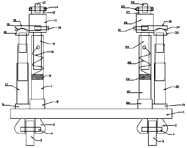
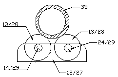
[0017] like figure 1 and figure 2 The shown vertical adjustable cable pay-off frame consists of a base 1, a roller positioning plate 2, a roller positioning shaft 4 and a moving wheel 3 arranged at the four corners of the bottom of the base 1, and a left pay-off arranged on the base 1. assembly, the right pay-off assembly, and the cable pay-off rod 35 used in conjunction with the left pay-off assembly and the right pay-off assembly; the left pay-off assembly includes the first positioning support column 5 arranged on the base 1, the A cylinder support plate 6, and the first positioning support sleeve 7 arranged on the first positioning support column 5, and the first spacer ring plate 8 arranged in the first positioning support sleeve 7, and the first positioning support sleeve 7 The first support column 9 used in conjunction with the first positioning plate 11 arranged on the first support column 9, the first roller positioning plate 12 arranged on the first positioning pla...


PUM


Abstract

The invention belongs to the technical field of cable installation accessory application and specifically relates to a vertical adjustable cable pay-off rack which is composed of a base, idler wheel location plates, idler wheel location shafts, movable wheels, a left pay-off assembly, a right pay-off assembly and a cable pay-off rod, wherein the idler wheel location plates, the idler wheel location shafts and the movable wheels are arranged at the four corners of the bottom of the base, the left pay-off assembly and the right pay-off assembly arranged on the base, and the cable pay-off rod ismatched with the left pay-off assembly and the right pay-off assembly to be used. The vertical adjustable cable pay-off rack disclosed by the invention has the beneficial effects: the whole structureslike the left pay-off assembly, the right pay-off assembly and the like are all cold-roll steel sheet or alloy stainless steel structure; service life is long, frequent overhaul is avoided, and a work efficiency is high; meanwhile, an inner structural design is reasonable, lifting operation can be performed by two air cylinders according to need, a cable assembling efficiency and whole structurepracticability are improved, and time and labor are saved; furthermore, the whole structures are stable, and an application range is wide.

Description

technical field [0001] The invention belongs to the technical field of application of cable installation accessories, and in particular relates to a vertical adjustable cable pay-off rack, which can protect the safety of dragging operations during cable construction, reduce friction on cables, and at the same time perform fast and timely collection / retrieval It can be used for laying operations, and the safety of use is improved, and the installation of cables on / off is convenient, and the height can be adjusted according to needs. Background technique [0002] In recent years, with the continuous acceleration of China's electric power development, China's power grid has also developed rapidly. The operating voltage level of the power grid system has continued to increase, and the network scale has also continued to expand. Power grid and China Southern Power Grid have 6 large-scale regional power grids across provinces, and have basically formed a complete long-distance tra...

Claims


Application Information

Patent Timeline
Patent Type & Authority Applications(China)
IPC IPC(8): B65H49/20B65H49/32B65H49/36H02G1/00
Inventor 宗泽宇
Owner 泰州鑫源电气设备销售有限公司
Why Eureka
Try Eureka