Evaporating device and evaporating method

A technology of evaporation and evaporation source, applied in vacuum evaporation plating, sputtering plating, ion implantation plating, etc., can solve the problems of large range of plating rate jump, unstable plating rate monitoring, false plating rate, etc. The effect of achieving a stable evaporation rate

Active Publication Date: 2018-03-09
SHENZHEN CHINA STAR OPTOELECTRONICS SEMICON DISPLAY TECH CO LTD
View PDF4 Cites 16 Cited by
  • Summary
  • Abstract
  • Description
  • Claims
  • Application Information

AI Technical Summary

Problems solved by technology

After a period of time after heating, Li 2 O and Li 3 N will be evaporated and deposited on the crystal oscillator of the plating rate monitoring device, Li 2 O. Li 3 The densities of N and Li are different, but since the plating rate monitoring device calculates the plating rate according to the density of Li, there will be situations of unstable plating rate monitoring and false plating rates
[0008] figure 1 For the plating rate curve of lithium (Li) monitored by the plating rate monitoring device in the existing vapor deposition process, such as figure 1 As shown, since Li 2 O and Li 3 N will also be vapor deposited on the crystal oscillator of the plating rate monitoring device, so the Li plating rate monitored by the plating rate monitoring device has a relatively large jumping range, and the plating rate monitoring effect is not good.

Method used


Image

  • Evaporating device and evaporating method
  • Evaporating device and evaporating method
  • Evaporating device and evaporating method

Examples


Embodiment Construction

[0044] In order to further illustrate the technical means adopted by the present invention and its effects, the following describes in detail in conjunction with preferred embodiments of the present invention and accompanying drawings.

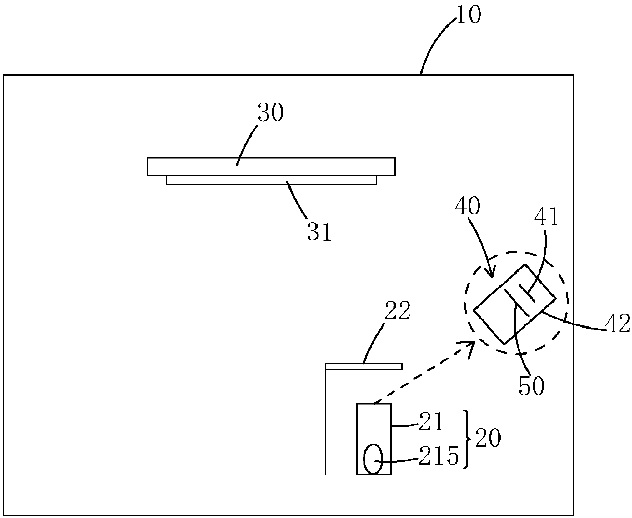
[0045] see Figure 2 to Figure 4 , the present invention firstly provides an evaporation device, comprising: a chamber body 10, an evaporation source 20 disposed in the chamber body 10, a waiting device disposed in the chamber body 10 and above the evaporation source 20 a coating substrate 30, and a coating rate monitoring device 40 disposed in the cavity 10 and above the evaporation source 20;

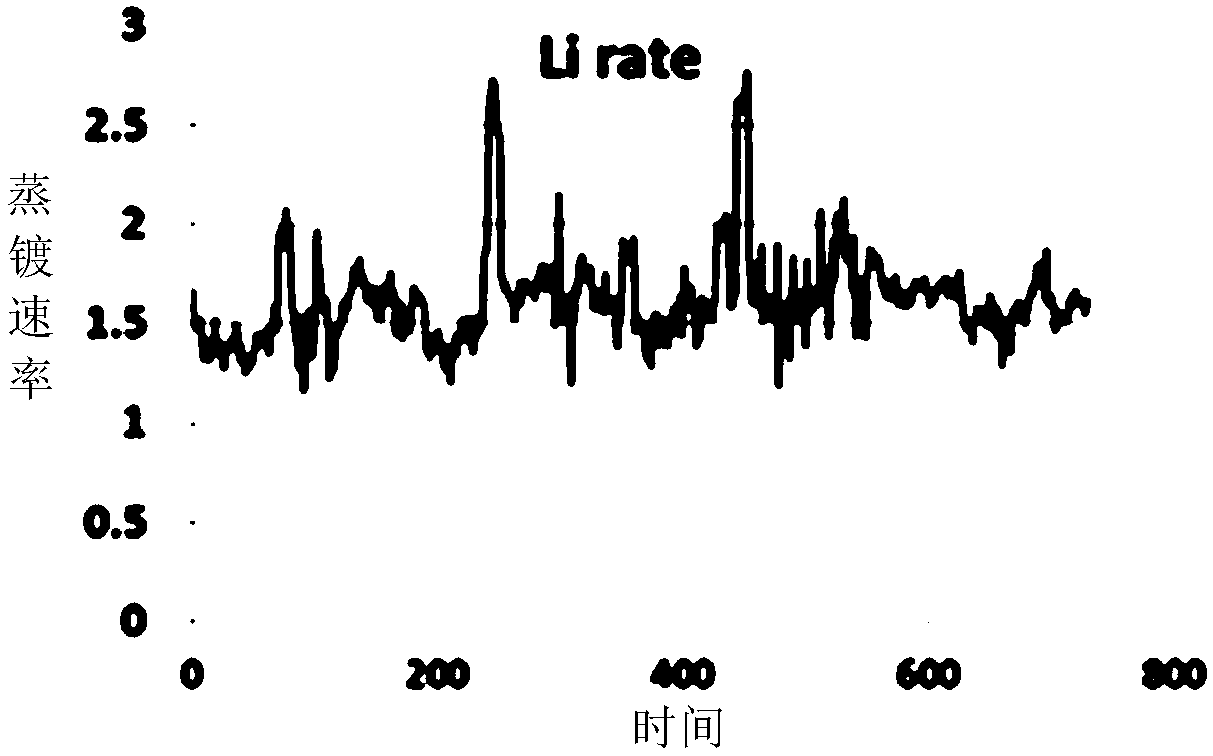
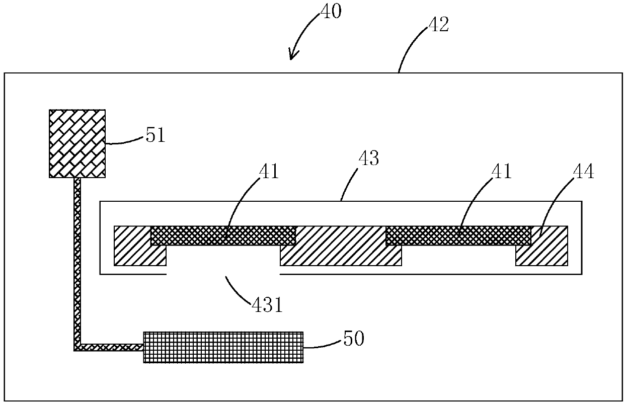
[0046] Described plating rate monitoring device 40 comprises crystal oscillator plate 41; Described crystal oscillator plate 41 is the probe of described plating rate monitoring device 40, and described plating rate monitoring device 40 is deposited on crystal oscillator plate 41 by the vapor deposition of the material film layer The rate is monitore...


PUM


Abstract

The invention provides an evaporating device and an evaporating method. According to the evaporating device disclosed by the invention, a crystal oscillator sheet baffle plate is arranged between an evaporation source and a crystal oscillator sheet, and the crystal oscillator sheet baffle plate can switch between two positions, namely a position shielding the crystal oscillator sheet and a position not shielding the crystal oscillator sheet; when the crystal oscillator sheet baffle plate is in the position shielding the crystal oscillator sheet, evaporation material deposits to the crystal oscillator sheet baffle plate, so as to prevent the evaporation material from depositing to the crystal oscillator sheet; and when the crystal oscillator sheet baffle plate is in the position not shielding the crystal oscillator sheet, the evaporation material deposits to the crystal oscillator sheet. When the evaporation device disclosed by the invention is applied to an evaporation process, in theinitial stage of evaporation, namely the evaporation stage of impurities on the surface of to-be-evaporated material, the crystal oscillator sheet baffle plate is in the position shielding the crystaloscillator sheet, so as to prevent impurities from depositing to the surface of the crystal oscillator sheet; and after evaporation of the impurities on the surface of the to-be-evaporated material is completed, the crystal oscillator sheet baffle plate is in the position not shielding the crystal oscillator sheet, and the evaporation material deposits to the surface of the crystal oscillator sheet, so that an evaporation rate monitoring device acquires a steady evaporation rate.

Description

technical field [0001] The invention relates to the field of display technology, in particular to an evaporation device and an evaporation method. Background technique [0002] Vacuum evaporation is an important thin film forming technology, which is widely used in industrial fields such as displays, electronic circuits, optics, and molds. For example, in organic light-emitting diode (OLED) display technology, organic materials are processed by vacuum evaporation. Film formation with metal materials to produce OLED components. [0003] The basic process of evaporation is as follows: the evaporation material is placed in the crucible of the evaporation chamber, and the chamber is evacuated to a certain degree of vacuum (E -5 After Pa), the crucible is heated to make the evaporation material reach a certain temperature, and the gas molecules of the evaporation material are ejected from the crucible, deposited on the substrate to form a target film, and also deposited on the c...

Claims


Application Information

Patent Timeline
Patent Type & Authority Applications(China)
IPC IPC(8): C23C14/24C23C14/54
CPCC23C14/24C23C14/546C23C14/14C23C14/564C23C14/243
Inventor 刘扬
Owner SHENZHEN CHINA STAR OPTOELECTRONICS SEMICON DISPLAY TECH CO LTD
Why Eureka
Try Eureka