Eureka AIR delivers breakthrough ideas for toughest innovation challenges, trusted by R&D personnel around the world.

Dyeing and drying equipment of colored yarns for spinning

A drying equipment and color technology, applied in the direction of processing textile material equipment configuration, processing textile material carrier, spraying/jetting textile material processing, etc. wait together

Active Publication Date: 2018-03-09
浙江森创服装股份有限公司
View PDF3 Cites 13 Cited by
  • Summary
  • Abstract
  • Description
  • Claims
  • Application Information

AI Technical Summary

Problems solved by technology

[0006] In order to overcome the disadvantages that the dyestuff cannot be completely attached to the colored thread when the colored thread is dyed, and the colored thread is not dried in time after dyeing, the technical problem to be solved by the present invention is to provide Dye can be completely attached to the colored thread, and can be dried in time after dyeing so that the colored thread will not stick together. A kind of textile color thread dyeing and drying equipment

Method used


Image

  • Dyeing and drying equipment of colored yarns for spinning
  • Dyeing and drying equipment of colored yarns for spinning
  • Dyeing and drying equipment of colored yarns for spinning

Examples


Embodiment 1

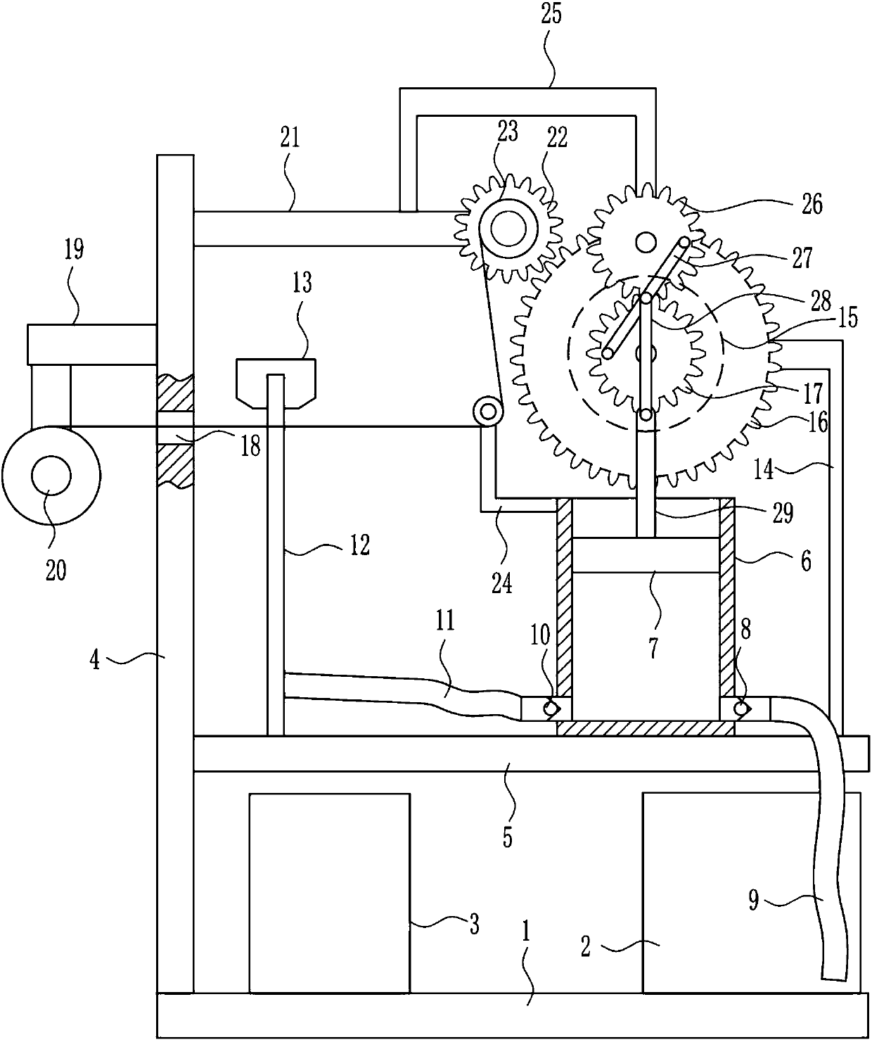
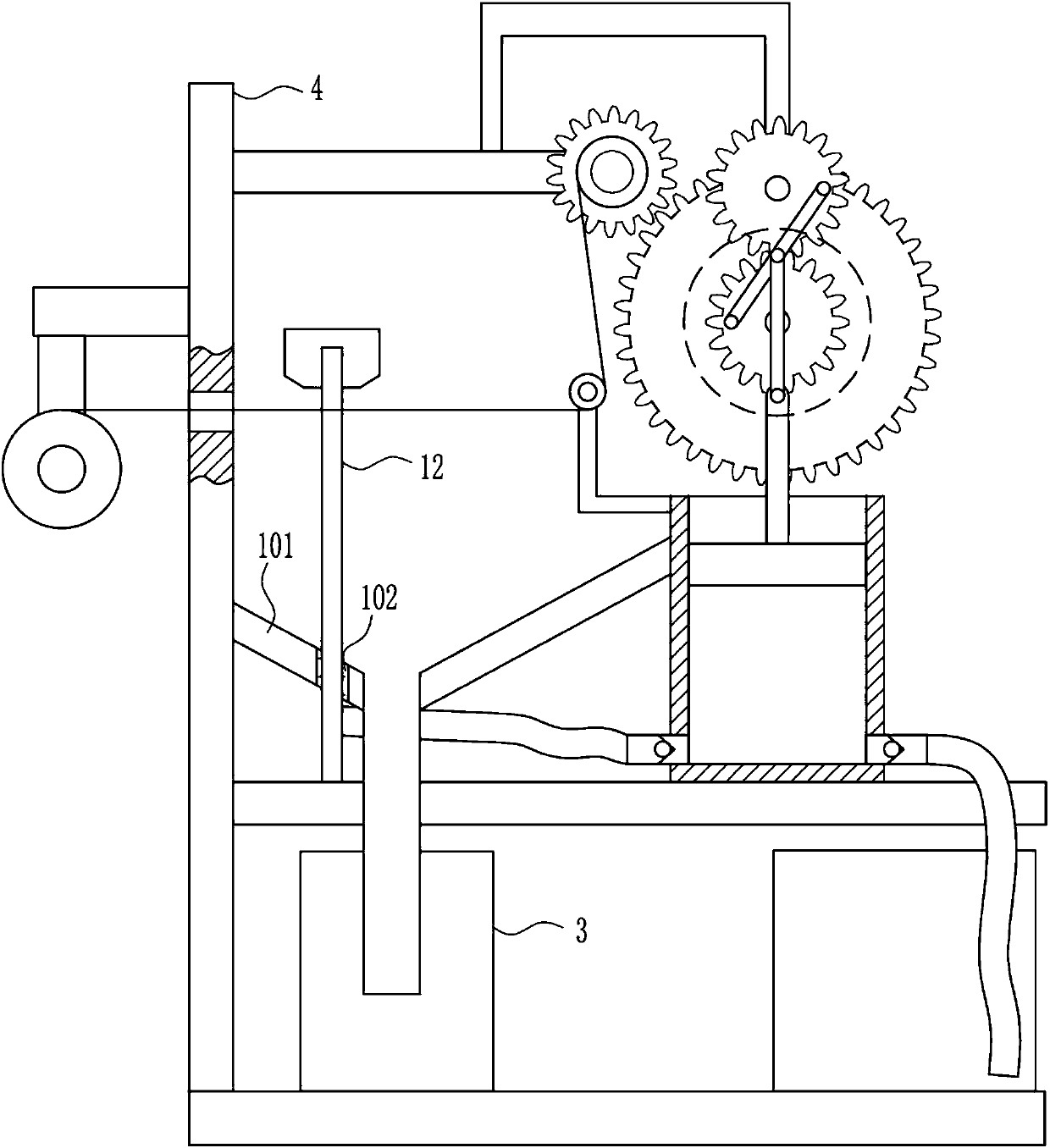
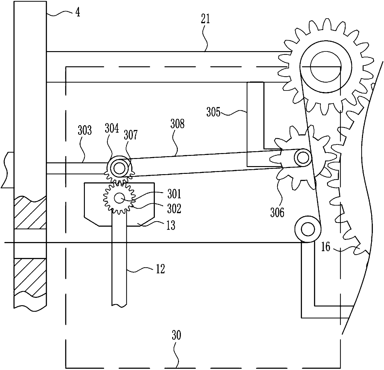
[0028] A kind of textile color thread dyeing and drying equipment, such as Figure 1-5 As shown, it includes a bottom plate 1, a dye box 2, a collection box 3, a support plate 4, a fixed plate 5, a piston cylinder 6, a piston block 7, a first one-way valve 8, a suction pipe 9, and a second one-way valve 10 , infusion tube 11, connecting tube 12, nozzle 13, first L-shaped rod 14, electric wheel 15, first gear 16, second gear 17, connecting block 19, wire wheel placement plate 20, connecting rod 21, third gear 22. Winding wheel 23, fixed pulley 24, N-shaped bar 25, fourth gear 26, first rocking bar 27, second rocking bar 28 and push rod 29, dye box 2 is placed on the right side of base plate 1, base plate 1 A collection box 3 is placed on the upper left side, a support plate 4 is installed on the left side of the bottom plate 1 by welding, a fixing plate 5 is installed on the lower right side of the support plate 4 by welding, and the upper right side of the fixing plate 5 is we...

Embodiment 2

[0030] A kind of textile color thread dyeing and drying equipment, such as Figure 1-5 As shown, it includes a bottom plate 1, a dye box 2, a collection box 3, a support plate 4, a fixed plate 5, a piston cylinder 6, a piston block 7, a first one-way valve 8, a suction pipe 9, and a second one-way valve 10 , infusion tube 11, connecting tube 12, nozzle 13, first L-shaped rod 14, electric wheel 15, first gear 16, second gear 17, connecting block 19, wire wheel placement plate 20, connecting rod 21, third gear 22. Winding wheel 23, fixed pulley 24, N-shaped bar 25, fourth gear 26, first rocking bar 27, second rocking bar 28 and push rod 29, dye box 2 is placed on the right side of base plate 1, base plate 1 A collection box 3 is placed on the upper left side, a support plate 4 is installed on the left side of the bottom plate 1 by welding, a fixing plate 5 is installed on the lower right side of the support plate 4 by welding, and the upper right side of the fixing plate 5 is we...

Embodiment 3

[0033] A kind of textile color thread dyeing and drying equipment, such as Figure 1-5 As shown, it includes a bottom plate 1, a dye box 2, a collection box 3, a support plate 4, a fixed plate 5, a piston cylinder 6, a piston block 7, a first one-way valve 8, a suction pipe 9, and a second one-way valve 10 , infusion tube 11, connecting tube 12, nozzle 13, first L-shaped rod 14, electric wheel 15, first gear 16, second gear 17, connecting block 19, wire wheel placement plate 20, connecting rod 21, third gear 22. Winding wheel 23, fixed pulley 24, N-shaped bar 25, fourth gear 26, first rocking bar 27, second rocking bar 28 and push rod 29, dye box 2 is placed on the right side of base plate 1, base plate 1 A collection box 3 is placed on the upper left side, a support plate 4 is installed on the left side of the bottom plate 1 by welding, a fixing plate 5 is installed on the lower right side of the support plate 4 by welding, and the upper right side of the fixing plate 5 is we...


PUM


Abstract

The invention relates to spinning equipment and in particular relates to dyeing and drying equipment of colored yarns for spinning. Aiming at solving the technical problems, the invention provides thedyeing and drying equipment of the colored yarns for spinning, which has the advantages that dyestuff can be completely attached on the colored yarns and the colored yarns can be dried by blowing intime after dyeing and are not stuck together. In order to solve the technical problems, the invention provides the dyeing and drying equipment of the colored yarns for spinning; the dyeing and dryingequipment comprises a bottom plate, a dyeing box, a collection box, a supporting plate and the like; the dyeing box is arranged at the right side on the bottom plate; the collection box is arranged atthe left side on the bottom plate; the supporting plate is mounted at the left side on the bottom plate through a welding manner; a fixed plate is mounted below the right side of the supporting platethrough the welding manner. By adopting the dyeing and drying equipment of the colored yarns for spinning, provided by the invention, the effects that the dyestuff can be completely attached on the colored yarns and the colored yarns can be dried by blowing in time after dyeing and are not stuck together are realized; an electric wheel drives a spraying nozzle to spray out the dyestuff and the spraying nozzle is driven to rotate so that the dyestuff can be completely attached to the colored yarns.

Description

technical field [0001] The invention relates to a textile equipment, in particular to a textile color thread dyeing and drying equipment. Background technique [0002] The original meaning of textile is taken from the general term of spinning and weaving, but with the continuous development and improvement of the textile knowledge system and subject system, especially after the emergence of non-woven textile materials and three-dimensional composite weaving technologies, textile is not only the traditional spinning and weaving Weaving also includes non-woven technology, three-dimensional weaving technology, electrostatic nano-netting technology, etc. [0003] At present, when dyeing colored threads for textiles, many of them will have this problem, that is, in the dyeing process, the colored threads cannot be dyed evenly, that is to say, the dye cannot be completely attached to the colored threads In addition, after the dyeing is completed, it is not possible to blow dry in...

Claims


Application Information

Patent Timeline
Patent Type & Authority Applications(China)
IPC IPC(8): D06B1/02D06B15/09D06B23/04D06B23/20
CPCD06B1/02D06B15/09D06B23/04D06B23/20
Inventor 乐甜桃叶倩宸刘玉萍
Owner 浙江森创服装股份有限公司
Why Eureka
Eureka Blog
Learn More