
Automatic oil extraction pump

An oil production pump and controller technology, applied to pumps, pump components, pressure pumps, etc., can solve problems such as wasted labor, partial wear of plungers and pump barrels, adverse effects on normal production of oil wells, etc., and achieve beautiful design and compact structure. Effect

Inactive Publication Date: 2018-03-09
黄建辉
View PDF0 Cites 0 Cited by
  • Summary
  • Abstract
  • Description
  • Claims
  • Application Information

AI Technical Summary

Problems solved by technology

[0003] The oil extraction pump is the main core device for oil extraction. There are existing oil extraction pumps used in oil wells. The plunger in the pump barrel is an ordinary plunger. During the extraction of scale and sandy oil wells, the plunger and pump barrel Partial wear is caused. When the plunger reciprocates up and down in the pump barrel, dirt or sand will inevitably enter the gap between the pump barrel and the plunger in the oil well pump system, which will easily cause the pump barrel and plunger to get stuck. The dead phenomenon occurs, which has a negative impact on the normal production of oil wells and seriously restricts the benefits of oilfield development.
At the same time, the design of these oil extraction pumps is simple, the structure is very primitive, and the extraction efficiency and function need to be improved. With the continuous complexity and deterioration of the oil extraction environment, the traditional oil extraction pumps have gradually been unable to adapt to the modern oil extraction environment. And most of the extraction pumps need too many people to waste too much labor. For this reason, we propose an automatic oil extraction pump

Method used


Image

  • Automatic oil extraction pump
  • Automatic oil extraction pump

Examples


Embodiment Construction

[0015] The following will clearly and completely describe the technical solutions in the embodiments of the present invention with reference to the accompanying drawings in the embodiments of the present invention. Obviously, the described embodiments are only some, not all, embodiments of the present invention. Based on the embodiments of the present invention, all other embodiments obtained by persons of ordinary skill in the art without making creative efforts belong to the protection scope of the present invention.

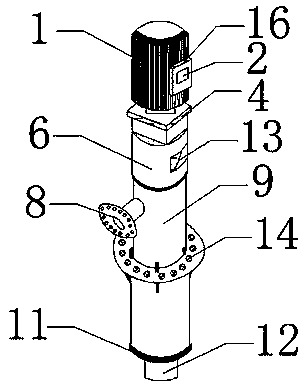
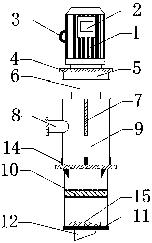
[0016] The present invention provides such Figure 1-2 A kind of automatic oil recovery pump shown, comprises motor 1, telescopic pipe 10 and controller 16, and the outer side of described motor 1 is fixedly connected with controller 16, and described controller 16 includes automatic switch, monitor and alarm, and described The outside of the controller 16 is provided with a casing, and there is a protective film outside the casing, the outside of the controll...


PUM


Abstract

The invention discloses an automatic oil extraction pump, which comprises a motor, a telescopic tube and a controller. The outer side of the motor is fixedly connected with the controller, and a liquid crystal display is arranged on the outer side of the controller. The right side of the motor is welded to a handle. The lower part of the motor is fixedly connected with the fixed frame by screws, and the lower part of the fixed frame is movably connected with the connecting pipe. A fan chamber is arranged under the connecting pipe, and an air outlet is opened on the outside of the fan chamber. Shaft, the lower part of the connecting pipe is fixedly connected with the cavity by screws, the left side of the cavity is welded to the oil outlet, the lower part of the cavity is fixedly connected with the fixed plate by screws, and a telescopic tube is arranged under the fixed plate. The lower part of the telescopic tube is flexibly connected with the sealing ring. The automatic oil production pump has a beautiful design and a compact structure, and realizes the purpose of intelligent automatic control by using a controller to control equipment and a liquid crystal display.

Description

technical field [0001] The invention belongs to the technical field of oil extraction pumps, in particular to an automatic oil extraction pump. Background technique [0002] Petroleum is an indispensable energy or resource for the development of modern society. After exploitation and refining, petroleum can be divided into various products such as gasoline, aviation kerosene, diesel oil, and engine oil, which provide energy for almost all machines such as automobiles, airplanes, and ships. Petroleum can be formed after tens of millions of years, and it is formed from the decay of trees in the Paleozoic Era. Ordinary oil is buried underground or under the seabed. To extract oil from the ground or seabed, various equipment and devices are required. [0003] The oil extraction pump is the main core device for oil extraction. There are existing oil extraction pumps used in oil wells. The plunger in the pump barrel is an ordinary plunger. During the extraction of scale and sandy...

Claims


Application Information

Patent Timeline
Patent Type & Authority Applications(China)
IPC IPC(8): F04F3/00
CPCF04F3/00
Inventor 黄建辉
Owner 黄建辉
Learn More