
Lossless detector and manufacturing method thereof

A detector, lossless technology, applied in the field of lossless detector and its manufacturing, can solve the problems of troublesome assembly operation, inability to reuse, increase production cost, etc.

Pending Publication Date: 2018-03-09
WEIHAI SUNFULL GEOPHYSICAL EXPLORATION EQUIP
View PDF0 Cites 0 Cited by
  • Summary
  • Abstract
  • Description
  • Claims
  • Application Information

AI Technical Summary

Problems solved by technology

[0003] The path between the positive and negative poles of the existing detector is: positive terminal - upper outer contact piece - upper spring piece - welding one end of the enameled wire - welding the other end of the enameled wire - lower spring piece - lower contact piece—lower yoke—magnetic steel—upper yoke—upper inner contact piece—negative terminal, in which the conduction between the enameled wire and the spring piece is achieved by pressing the spring piece with the snap ring, and then soldering. The spring sheet is related to many indicators of the geophone. During the production process, due to various factors, some unqualified products will be produced. As long as the unqualified products are repaired, the spring sheet usually needs to be replaced. Once the spring sheet is replaced, because it is different from The enameled wire is connected by welding, so these spring pieces and snap rings are scrapped and cannot be reused. When there are many repairs, the entire coil will be scrapped. Not only the assembly operation is troublesome, the efficiency is low, and the production cost is greatly increased.

Method used


Image

  • Lossless detector and manufacturing method thereof
  • Lossless detector and manufacturing method thereof
  • Lossless detector and manufacturing method thereof

Examples


Embodiment Construction

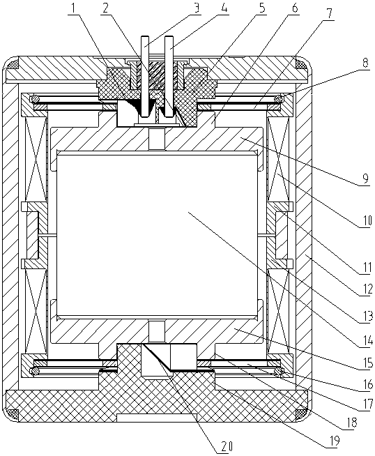
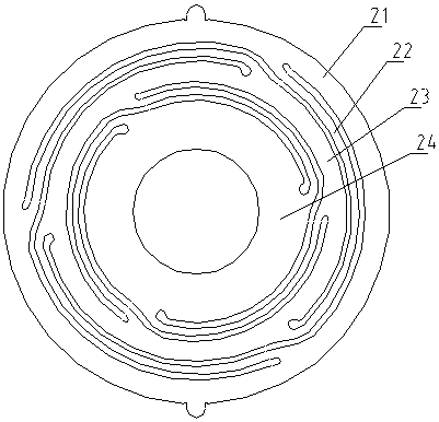
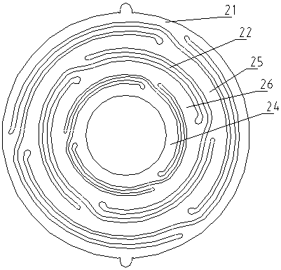
[0020] Such as figure 1 The lossless detector shown includes an outer shell 12, a magnetic steel 14 is arranged in the middle of the outer shell 12, an upper yoke 9 and a lower yoke 15 are respectively arranged on the upper and lower ends of the magnetic steel 14, and the upper middle of the upper yoke 9 is An upper spring piece 7 is fixed between the upper side of the outer shell, and the upper spring piece 7 is ring-shaped. The inner side of the annular upper spring piece is fixed between the upper end of the upper yoke and the outer shell. An insulating layer is provided between them; a lower spring piece 17 is fixed between the middle part of the lower end of the lower yoke 15 and the lower side of the outer casing, the lower spring piece 17 is ring-shaped, and the inner side of the ring of the lower spring piece 17 is fixed between the lower end of the lower yoke iron and the outer casing. There is an insulating layer between the spring piece, the lower yoke and the outer...


PUM


Abstract

A lossless detector relates to the field of detectors. The lossless detector comprises an outer casing body, a magnetic steel, an upper yoke, a lower yoke and an upper leaf spring. A positive terminaland a negative terminal are fixed on the outer casing body, the positive terminal is connected with the upper leaf spring through an upper outer contact piece, the negative terminal is connected withthe upper yoke through an upper inner contact piece, and the lower yoke is connected with a lower leaf spring through a lower contact piece; and winding windows of an upper coil frame and a lower coil frame are brushed with insulation layers, and two ends of the coils are respectively welded with the upper coil frame and the lower coil frame. During manufacture, the insulation layers are brushedon the surface of the winding windows; an enameled wire is wound in the winding windows of the upper coil frame and the lower coil frame; and two ends of the enameled wire are respectively welded withthe upper coil frame and the lower coil frame. The lossless detector greatly reduces the assembly skill requirements, and the welding operation during the coil winding is simple and easy to grasp sothat the assembly production efficiency of the detector can be greatly improved.

Description

technical field [0001] The invention relates to the field of geophones, in detail, it is a non-loss geophone with simple structure, convenient processing, high assembly efficiency, simple and convenient maintenance, reusable components and a manufacturing method thereof. Background technique [0002] We know that the structure of the existing geophone is as follows: an outer casing is provided, a magnetic steel is arranged in the middle of the outer casing, an upper yoke and a lower yoke are respectively arranged on the upper and lower ends of the magnetic steel, and an upper yoke is arranged in the middle of the upper end of the upper yoke. Press the convex ring, the upper spring piece is fixed between the upper pressing convex ring and the outer shell, an insulating layer is provided between the upper spring piece and the upper yoke, the upper spring piece is ring-shaped, and the ring-shaped inner side of the upper spring piece is fixed on the upper yoke Between the upper ...

Claims


Application Information

Patent Timeline
Patent Type & Authority Applications(China)
IPC IPC(8): G01D5/12
CPCG01D5/12
Inventor 任强陈春国戚全
Owner WEIHAI SUNFULL GEOPHYSICAL EXPLORATION EQUIP
Learn More