Infrared double-view-field quickly-switched camera lens

A fast switching, dual field of view technology, applied in the optical field, can solve the problems of high cost, short system switching time, difficult processing and assembly, etc., and achieve the effect of resisting severe external vibration, convenient daily maintenance, and high reliability.

Active Publication Date: 2018-03-09
湖南华南光电(集团)有限责任公司
View PDF5 Cites 5 Cited by
  • Summary
  • Abstract
  • Description
  • Claims
  • Application Information

AI Technical Summary

Problems solved by technology

[0003] The current infrared dual-field optical lenses are mainly divided into two categories: the first category is the axial movement type, that is, the focal length of the optical system is changed by changing the axial distance of the lens group. The disadvantage is that the axial size is large and the mechanical structure Complicated, low stability accuracy, long zooming time, difficult processing and assembly, which increases production costs, and difficult to control focal length accuracy after zooming
The second type is the switching type, that is, the focal length of the optical system is changed by switching the lens group in the optical system. The characteristic of this type of optical system is that there is no moving optical element in the small field of view optical path, and the optical axis of the optical system has good stability. The switching time of the system is short and the transmittance is high; however, in order to ensure the stability of the optical axis, the lens needs to be equipped with a corresponding locking mechanism after switching, because the number of electronic components used is large, the volume is large, and the cost is high; Therefore, in some special application scenarios, the dual-field infrared thermal imager cannot be equipped with the function of quickly switching the field of view.

Method used


Image

  • Infrared double-view-field quickly-switched camera lens
  • Infrared double-view-field quickly-switched camera lens
  • Infrared double-view-field quickly-switched camera lens

Examples


Embodiment Construction

[0036] Embodiments of the present invention will be further described below in conjunction with the accompanying drawings.

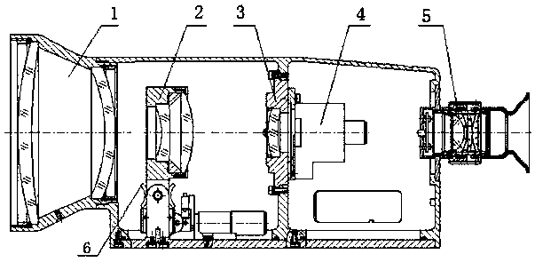
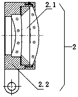
[0037] The optical system of an infrared dual-field of view fast switching lens in the present invention is a passive athermal switching infrared dual-field of view infrared optical system, such as Image 6 As shown, the optical system includes a front fixed lens group 1, a zoom lens group 2.1, and a rear fixed lens group 3. The distance between the zoom lens group 2.1 and the rear fixed lens group 3 is relatively large to ensure that there is enough space for the zoom lens Mirror group 2.1. The zoom lens group 2.1 is composed of a zoom negative lens and a positive zoom lens, ensuring that the new image plane position after it is screwed into the optical path remains unchanged from the image plane position of the optical path before it is screwed in. At the same time, through the matching of lens parameters and lens barrel materials, the chromatic aberr...


PUM


Abstract

The invention discloses an infrared double-view-field quickly-switched camera lens which comprises a base plate, a front fixed lens set, an overturnable lens set, a rear fixed lens set, a non-refrigerating infrared movement, an eyepiece assembly, a groove wheel mechanism, a bevel gear set and a driving assembly. The overturnable lens set and the groove wheel mechanism are connected with a mountingseat through a connecting shaft, and the mounting seat is fixed to the base plate. The bevel gear set consists of a bevel gear I and a bevel gear II which are meshed with each other, wherein the bevel gear I is fixed to the end of the groove wheel mechanism through a connecting shaft, the bevel gear II is installed at the end of the driving assembly through a transmission shaft, and the driving assembly is fixed to the base plate and drives the groove wheel mechanism to operate through the bevel gear set. The infrared double-view-field quickly-switched camera lens utilizes the groove wheel mechanism to drive the overturnable lens set to achieve overturning in the range from 0 degree to 90 degrees, the switching time is short, a self-locking function is strong, and the camera lens can resist outside violent vibration and is high in use reliability.

Description

technical field [0001] The invention relates to the field of optics, in particular to an infrared dual-field fast switching lens. Background technique [0002] The infrared dual-field optical system is an infrared optical system that integrates the advantages of infrared technology and zoom optical system. Because it has the characteristics of high transmittance, low cost, and can realize the conversion of field of view, it is widely used in remote sensing, early warning, and reconnaissance. , infrared imaging guidance and other fields have a wide range of applications. Due to the needs of the application, the infrared dual-field of view optical system generally has two fields of view, one large and one small. The large field of view is used to search for suspicious targets in a large space, and the small field of view is used to identify, track or aim. [0003] The current infrared dual-field optical lenses are mainly divided into two categories: the first category is the...

Claims


Application Information

Patent Timeline
Patent Type & Authority Applications(China)
IPC IPC(8): G03B17/14G02B7/02
CPCG02B7/023G03B17/14
Inventor 姜立伟李继泉吴军张格斐陈静胡春松胡婷龙炎邱党社谭祖安黄千里程翔胡民康
Owner 湖南华南光电(集团)有限责任公司
Why Eureka
Try Eureka