
A Fiber Image Processing Method Based on Nonuniformity Correction

A non-uniformity correction and image processing technology, which is applied in image data processing, image analysis, image enhancement, etc., can solve problems such as inability to process black spots in the fiber core, incomplete edges of fiber images, and easy judgment errors, etc., to achieve Eliminate dark spots and bright spots, accurate judgment, reasonable design effect

Active Publication Date: 2020-04-21
THE 41ST INST OF CHINA ELECTRONICS TECH GRP
View PDF4 Cites 0 Cited by
  • Summary
  • Abstract
  • Description
  • Claims
  • Application Information

AI Technical Summary

Problems solved by technology

This algorithm is prone to misjudgment when judging the position of the fiber, resulting in incomplete and mishandled fiber image edges
At the same time, the black spot at the fiber core cannot be processed

Method used


Image

  • A Fiber Image Processing Method Based on Nonuniformity Correction
  • A Fiber Image Processing Method Based on Nonuniformity Correction
  • A Fiber Image Processing Method Based on Nonuniformity Correction

Examples


Embodiment Construction

[0037] Below in conjunction with accompanying drawing and specific embodiment the present invention is described in further detail:

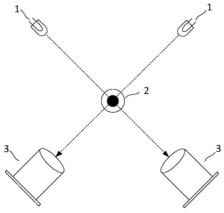
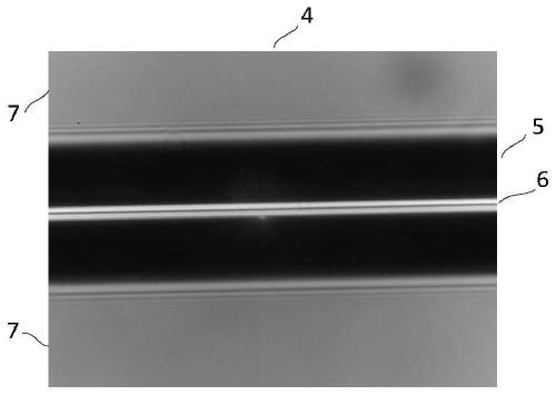
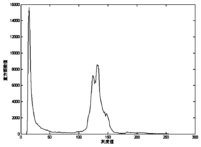
[0038] Such as figure 1 In the optical fiber microscopic imaging system shown, the light source 1 irradiates the optical fiber 2 along the horizontal direction, due to the difference in refractive index between the air, the fiber cladding and the fiber core, and the object distance between the core and the edge of the fiber relative to the high-power microscope 3 Different, so it will produce bright and dark images on the focal plane, when the average brightness of the background is 130, its dark spot optical fiber image is as figure 2 As shown, its grayscale histogram is as image 3 shown. The fiber image 4 displayed on the liquid crystal screen mainly includes three parts, namely the fiber cladding 5 , the fiber core 6 and the image background 7 . The range of the gray level of the fiber cladding 5 is far from the image background 7, so it...


PUM


Abstract

The invention discloses an optical fiber image processing method based on non-uniformity correction, which belongs to the field of optical fiber image processing. It includes segmenting the optical fiber cladding, optical fiber core and image background in the optical fiber image, and determining the gray areas that require non-uniformity correction. degree interval, according to the same optical fiber microscope, select images with different illumination intensities as calibration images and determine the calibration parameters. Use the calibration parameters to perform non-uniformity correction using a two-point correction algorithm. This method effectively removes black spots and bright spots in the background of optical fiber images while occupying less hardware resources, thereby reducing the interference of image defects on the identification of optical fiber types and positions, and improving the accuracy of optical fiber alignment.

Description

technical field [0001] The invention belongs to the field of optical fiber image processing, in particular to an optical fiber image processing method based on non-uniformity correction. Background technique [0002] During the working process of the optical fiber fusion splicer, dust or oil may adhere to the lens of the microscope objective lens, resulting in black spots or bright spots on the fiber image. Generally, there are two processing methods: the first is based on the calibration of two-point non-uniformity However, the general non-uniformity correction algorithm is only effective in the gray-scale range where the response area is approximately linear, and it will cause serious distortion when processing images with a wide gray-scale range. The second is to use hardware to process the source data of the optical fiber image. First, the position of the optical fiber in the image is judged, and then the area where the optical fiber is located is calibrated, and the ima...

Claims


Application Information

Patent Timeline
Patent Type & Authority Patents(China)
IPC IPC(8): G06T7/80G06T7/11G06T7/136G06T5/00
CPCG06T7/11G06T7/136G06T7/80G06T5/00
Inventor 何春尚守锋杨小光任晓楠
Owner THE 41ST INST OF CHINA ELECTRONICS TECH GRP
Learn More