Eureka AIR delivers breakthrough ideas for toughest innovation challenges, trusted by R&D personnel around the world.

Wire cutting machine

A technology of cutting machine and wire, which is applied in the direction of metal processing machinery parts, large fixed members, maintenance and safety accessories, etc., can solve the problems of low cutting efficiency, wire vibration, and affecting cutting accuracy, and achieve low production cost, simple structure, The effect of easy operation

Inactive Publication Date: 2018-03-13
南通冒氏智能装备有限公司
View PDF6 Cites 0 Cited by
  • Summary
  • Abstract
  • Description
  • Claims
  • Application Information

AI Technical Summary

Problems solved by technology

[0002] At present, the wire cutting technology and wire cutting machines on the market are widely used in all walks of life, but its cutting accuracy and cutting efficiency are difficult to be improved by a large length, which will always be limited due to various reasons, mainly as follows Question: 1) There are two types of wire-feeding mechanisms at present, one is step-driven fast wire-feeding, and the other is slow-feeding wire-feeding, but the stepping-driven fast wire-feeding machine tool equipment in these two methods is low in price and low in operating costs , but the processing is unstable and the accuracy of the processing size is poor. Although the slow-moving wire cutting machine is expensive, the processing is stable, and the dimensional accuracy is high, but the operating cost is high; 2) The chip removal effect of the conventional wire cutting machine is poor, resulting in easy Short circuits and frequent wire breakages occur, which eventually lead to low cutting efficiency; 3) The wire storage drum of the current cutting machine will be affected by the bed during the reversing process and cause vibration, and wire vibration will occur during cutting, which will affect the cutting accuracy; 4) In addition, some silk threads are easy to wear after long-term use, and manual inspection is required, but the naked eye inspection is judged by the operator's experience, which leads to errors and affects the final cutting effect, so it needs to be improved

Method used

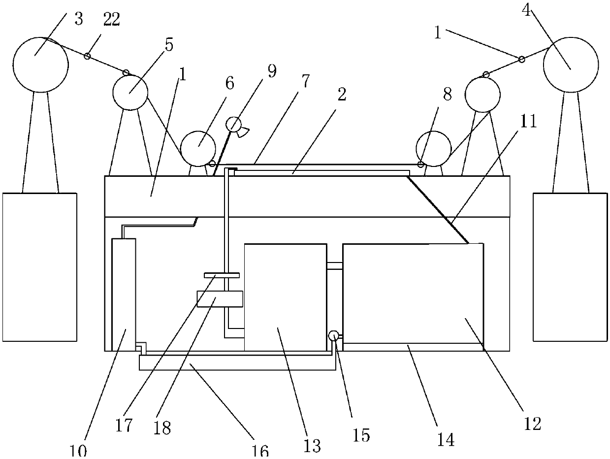
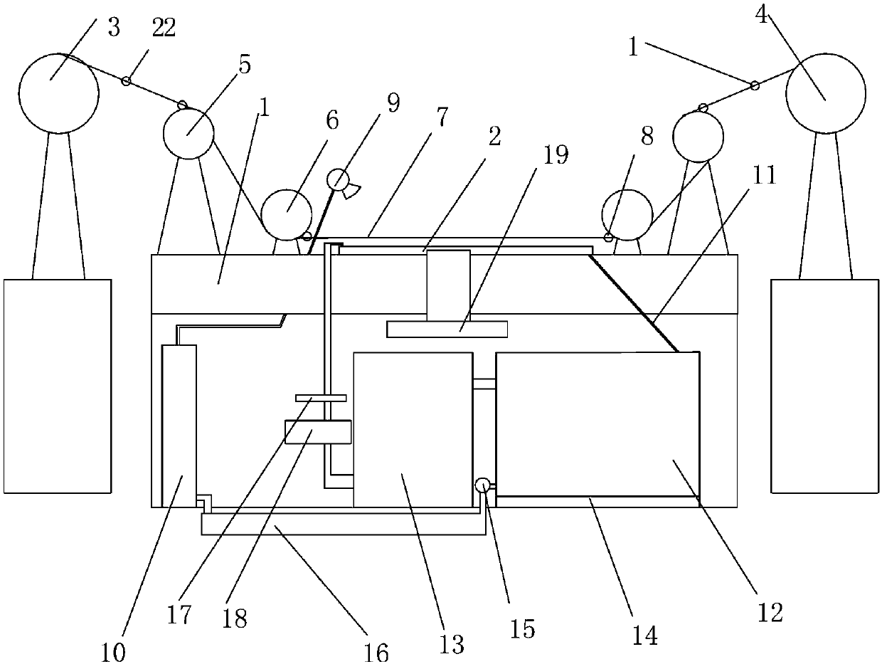
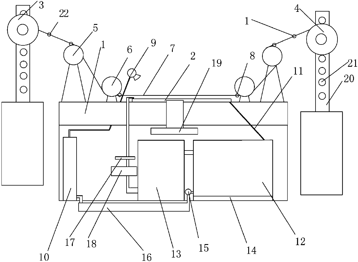

Image

  • Wire cutting machine
  • Wire cutting machine
  • Wire cutting machine

Examples


Embodiment 1

[0017] Such as figure 1 As shown, a wire cutting machine provided by this embodiment includes a bed 1, a workbench 2, a wire storage tube 3, a wire release tube 4, a wire guide wheel 5 and a cutting and cleaning device, and is characterized in that the working The table 2 is set on the bed 1, the wire storage cylinder 3 is detachably arranged on one side of the workbench 2, and the wire discharge cylinder 4 is detachably arranged on the other side of the workbench 2, and the wire storage cylinder 3 and the wire discharge The cylinder 4 controls its working rotation and reversing operation through a servo motor respectively. The godet wheels 5 include more than 3 numbers, and at least 2 of them are placed under the other godet wheels 5 as the bottom godet wheels 6, And the wire guide wheels 5 at the bottom are all parallel to each other on the same straight line, and all the wire guide wheels 5 and the wire storage tube 3 and the wire release tube 4 form a "凵"-shaped structure,...

Embodiment 2

[0021] Such as figure 2 As shown, the general structure of a wire cutting machine provided by this embodiment is the same as that of Embodiment 1, the difference is that, in order to facilitate positioning, the workbench 2 is arranged on the bed 1 through a lifting mechanism 19, and further, The lifting mechanism 19 is an air cylinder or a motor.

Embodiment 3

[0023] Such as image 3 As shown, the wire cutting machine provided by this embodiment is further convenient for positioning. A fixing frame 20 is respectively provided on both sides of the bed 1, and the wire storage tube 3 and the wire feeding tube 4 are slidably connected to each other. On the corresponding fixing frame 20 , positioning holes 21 are arranged at intervals in the fixing frame 20 , and the wire storage tube 3 and the wire releasing tube 4 are locked in the positioning holes 21 by locking pieces.

[0024] Further, to prevent jamming, there is a distance difference between the wire storage cylinder 3 and the wire delivery cylinder 4 .

[0025] This embodiment is simple in structure, easy to operate, low in price, low in production cost, and can adjust the height of the workbench according to needs, and monitor the silk thread in real time, and replace it later in case of wear and tear, and position the thread direction to prevent deviation It affects the cuttin...


PUM


Abstract

The invention discloses a wire cutting machine which comprises a nut and a lead screw. The nut comprises an outer nut body and an inner nut body. The outer nut body is arranged on the inner nut body in a sleeving manner. The inner nut body is arranged on the outer portion of the lead screw in a sleeving manner and can move on the lead screw. A spiral groove is formed in the inner nut body. An inclined cutting portion is arranged at the end of one side of the lead screw. An elastic locating part embedded in the cutting portion is arranged on the cutting portion. An arc groove carrying out pathguiding on the elastic locating part is formed in the outer nut body. A locating groove with the depth larger than that of the arc groove is formed in one end of the arc groove. A locating bearing isarranged on the contact face of the inner nut body and the outer nut body. The wire cutting machine is simple in structure, convenient to operate, low in price, reliable in performance and capable ofachieving the function of automatic limiting protection.

Description

technical field [0001] The invention relates to the technical field of wire cutting, in particular to a wire cutting machine. Background technique [0002] At present, the wire cutting technology and wire cutting machines on the market are widely used in all walks of life, but its cutting accuracy and cutting efficiency are difficult to be improved by a large length, which will always be limited due to various reasons, mainly as follows Question: 1) There are two types of wire-feeding mechanisms at present, one is step-driven fast wire-feeding, and the other is slow-feeding wire-feeding, but the stepping-driven fast wire-feeding machine tool equipment in these two methods is low in price and low in operating costs , but the processing is unstable and the accuracy of the processing size is poor. Although the slow-moving wire cutting machine is expensive, the processing is stable, and the dimensional accuracy is high, but the operating cost is high; 2) The chip removal effect ...

Claims


Application Information

Patent Timeline
Patent Type & Authority Applications(China)
IPC IPC(8): B23H7/02B23H7/26B23Q1/30B23Q11/00B23Q17/09
CPCB23H7/02B23H7/26B23Q1/30B23Q11/0042B23Q17/0957
Inventor 不公告发明人
Owner 南通冒氏智能装备有限公司
Why Eureka
Eureka Blog
Learn More