Ultrasonic vibration assistance laser boring method and device

A technology of ultrasonic vibration and auxiliary laser, used in laser welding equipment, welding equipment, metal processing equipment, etc., can solve the problems of easy adhesion of molten material, affecting the appearance of the inner wall of the hole, cracks, etc., so as to reduce internal defects and avoid disadvantages. Function and influence, the effect of improving the removal rate

Pending Publication Date: 2018-03-13
JIANGSU UNIV
View PDF7 Cites 11 Cited by
  • Summary
  • Abstract
  • Description
  • Claims
  • Application Information

AI Technical Summary

Problems solved by technology

[0003] The current laser drilling uses the laser as the heat source to process the workpiece, and the light energy is converted into heat energy. After absorbing the heat energy, the material heats up and forms a molten pool on its surface, and the surface material is continuously melted and removed. The disadvantage of this method is: the material During the laser drilling process, it will go through a complex process of high temperature melting and cooling and condensation, and finally a recast layer will be formed on the micropore wall. Due to the recoil pressure, the melt in the hole will flow and splash, and the splashed melt will easily Adhesion to the small hole wall produces cracks and affects the shape of the inner wall of the hole

Method used


Image

  • Ultrasonic vibration assistance laser boring method and device
  • Ultrasonic vibration assistance laser boring method and device
  • Ultrasonic vibration assistance laser boring method and device

Examples


Embodiment Construction

[0044] The present invention will be further described below with reference to the drawings and specific embodiments, but the protection scope of the present invention is not limited to this.

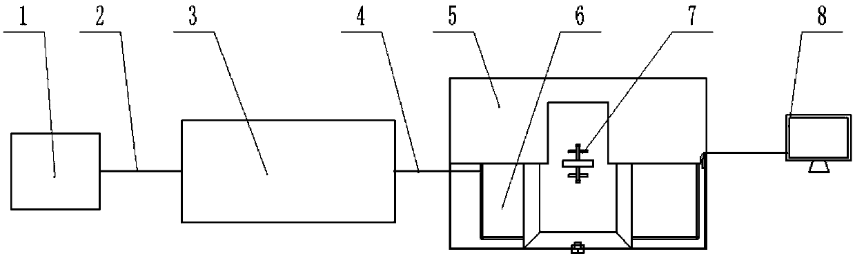
[0045] Such as figure 1 As shown, an ultrasonic vibration assisted laser drilling device according to the present invention includes a power source 1, an ultrasonic generator 3, an ultrasonic vibration auxiliary device clamping unit 5, an ultrasonic vibration generating unit 6, a workpiece clamping unit 7, and a water depth detection The unit 8 and the laser generating unit, the power supply 1 is connected to the ultrasonic generator 3 through the first wire 2, the ultrasonic generator 3 is connected to the ultrasonic vibration generating unit 6 through the second wire 4, the ultrasonic generator 3 and the ultrasonic vibration generating unit 6 generate The ultrasonic power can be adjusted.

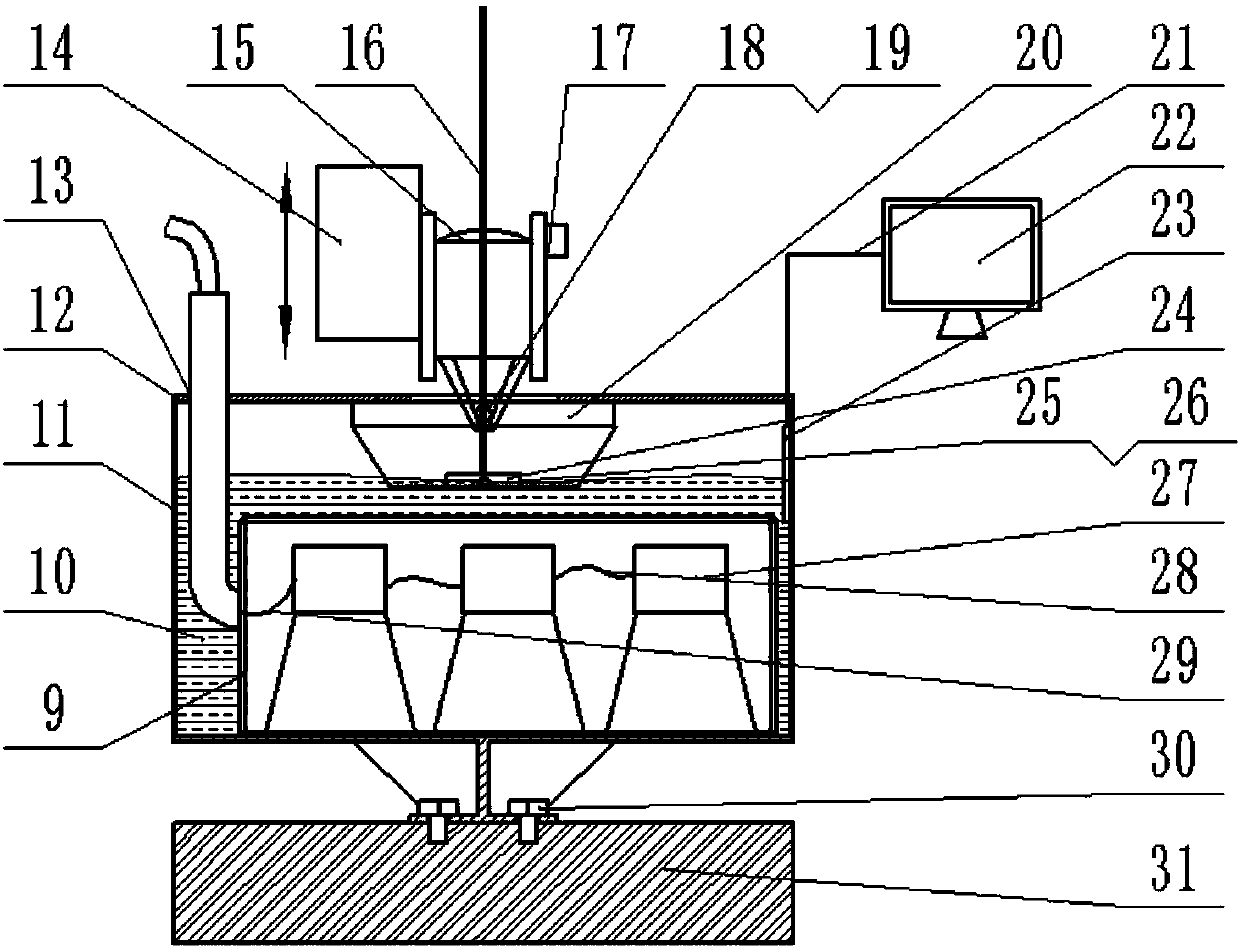
[0046] Such as figure 2 As shown, the function of the ultrasonic vibration generating unit 6 is to ...


PUM


Abstract

The invention provides an ultrasonic vibration assistance laser boring method and device. The device comprises a power source, an ultrasonic generator, an ultrasonic vibration auxiliary device clamping unit, an ultrasonic vibration generation unit, a workpiece clamping unit and a laser generation unit; the power source is connected with the ultrasonic generator through a first electric wire, the ultrasonic generator is connected with the ultrasonic vibration generation unit through a second electric wire, a workpiece is mounted on the workpiece clamping unit, and when laser boring is carried out, ultrasonic vibration generated by the ultrasonic vibration generation unit can act on the workpiece in the direction perpendicular to the machining surface of the workpiece. A melting material ina hole can be discharged while laser boring is carried out, through the ultrasonic vibration assistance effect, removal of slag can be accelerated, the removal rate of the slag can be improved, the phenomenon that melt is solidified on the hole wall again to form a re-casting layer is reduced or avoided, meanwhile, ultrasonic vibration can obviously improve the hole wall surface quality, the laserboring quality can be improved, and the boring efficiency is improved.

Description

Technical field [0001] The invention relates to advanced laser manufacturing and processing, belonging to the field of laser manufacturing and processing, and in particular to an ultrasonic vibration assisted laser drilling method and device. Background technique [0002] With the rapid development of modern industry and science and technology, more and more materials with high hardness and high melting point are used, and traditional processing methods can no longer meet certain process requirements. Laser drilling is the earliest practical laser processing technology and one of the main application areas of laser processing. Laser drilling refers to the use of a pulsed laser beam to irradiate the surface of the workpiece. Because the energy density of the focused laser beam is extremely high, the temperature at the focal point will instantly reach thousands of degrees Celsius. The workpiece material will be rapidly melted under the action of this high temperature. , Vaporizati...

Claims


Application Information

Patent Timeline
Patent Type & Authority Applications(China)
IPC IPC(8): B23K26/382B23K26/70B23K26/122
CPCB23K26/1224B23K26/382B23K26/702
Inventor 王后孝朱苏凯石春辉夏凯波任乃飞
Owner JIANGSU UNIV
Why Eureka
Try Eureka