
Patsnap Eureka
For R&D, Patsnap Eureka makes reading and utilizing patents & technical documents easy.
Patsnap Eureka AIR
Designed for self-driven R&D workflows. Generate viable solutions, solve complex R&D challenges, empower your innovation with AI.

Patsnap Eureka Materials
Designed for material experts only. Revolutionize your material R&D, from search, analyze, to developing new materials.

TechResearch
Generate reliable direction feasibility study reports for your R&D in just a few steps.

TechSeek
Discover and master advanced knowledge NOW. Basics, ideas, possibilities, all at once.

TechMind
As an expert in R&D Theories, TechMind can generates customized viable solutions instantly.

TechRisk
Analyze your overall solution with one click, know your potential R&D risks in advance.

TechMonitor
Get weekly tech updates, stay abreast of the latest tech innovations and key insights.
Centering pin positioning guide structure
A technology of positioning guide and centering needle, which is applied in binding and other directions, can solve the problems of increasing the overall cost of the binding machine, affecting the riveting quality, affecting the appearance of documents, etc., and achieves the effect of simple structure, good riveting quality and long service life
- Summary
- Abstract
- Description
- Claims
- Application Information
AI Technical Summary
Problems solved by technology
Method used
Image

Examples
Embodiment Construction
[0019] In order to enable those skilled in the art to better understand the technical solution of the present invention, the product of the present invention will be further described in detail below in conjunction with the embodiments and accompanying drawings.
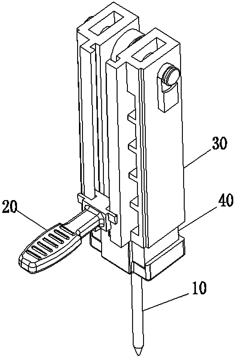
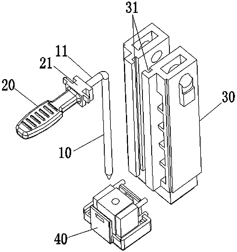
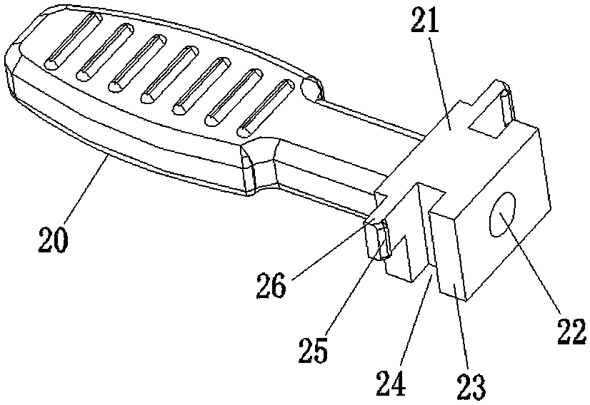
[0020] Such as figure 1 and figure 2 As shown, a centering pin 10 positioning guide structure includes a centering pin 10 located above the rivet head assembly 40, the centering pin 10 is located in the middle of the drive block 30 above the rivet head assembly 40, and the centering pin 10 The upper end of the upper end is provided with a horizontal bending portion 11 bent forward, and the outer end of the horizontal bending portion 11 is provided with a handle 20 made of elastic plastic, and one end of the handle 20 connected to the horizontal bending portion 11 A sliding positioning part 21 is provided, and the two sides of the front end of the driving block 30 are provided with slide grooves 31 oppositely distri...
PUM
 Abstract
Description
Claims
Application Information
 - R&D Engineer
- R&D Manager
- IP Professional
- Industry Leading Data Capabilities
- Powerful AI technology
- Patent DNA Extraction
Browse by: Latest US Patents, China's latest patents, Technical Efficacy Thesaurus, Application Domain, Technology Topic, Popular Technical Reports.
© 2024 PatSnap. All rights reserved.Legal|Privacy policy|Modern Slavery Act Transparency Statement|Sitemap|About US| Contact US: help@patsnap.com