
New energy electric vehicle thermal management system and thermal management method

A thermal management system, a technology for electric vehicles, applied in the field of thermal management, can solve the problems of heat waste, large power consumption, and ineffective management of heat, and achieve the effect of improving energy saving and reducing energy consumption.

Pending Publication Date: 2018-03-13
SHANDONG LONGERTEK TECH CO LTD
View PDF0 Cites 10 Cited by
  • Summary
  • Abstract
  • Description
  • Claims
  • Application Information

AI Technical Summary

Problems solved by technology

At present, for new energy vehicles, only the thermal management of the battery is generally carried out, and the refrigerant circulation circuit composed of the compressor, condenser, throttling element and evaporator is used to cool the battery, and at the same time, the heating circuit is used to heat the battery at low temperature. The battery is kept within the normal operating temperature range, but the heat of the battery is not effectively recovered and reused, resulting in waste of heat. At the same time, as long as the battery needs to cool down, the compressor in the refrigerant circulation circuit starts, which consumes a lot of power. Moreover, the new energy vehicles in the prior art have not effectively managed the heat of the motor and electronic control components.

Method used


Image

  • New energy electric vehicle thermal management system and thermal management method

Examples


Embodiment Construction

[0021] Below in conjunction with accompanying drawing and specific embodiment the present invention is described in further detail:

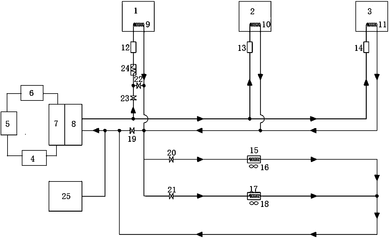
[0022] Such as figure 1 As shown, a thermal management system for a new energy electric vehicle provided by the present invention performs unified thermal management on the three major heating elements on the vehicle, namely the battery 1, the motor 2, and the electric control 3. The thermal management system includes a refrigerant circulation circuit, a coolant circulation circuit and a battery heating circuit.

[0023] Wherein, the refrigerant circulation circuit is composed of a compressor 4 , a condenser 5 , a throttling element 6 and an evaporator 7 which are sequentially connected through refrigerant pipelines.

[0024] The cooling liquid circulation loop includes a first heat exchanger 8 connected in sequence through pipelines, a second heat exchanger installed inside the heating element, and a cooling device. An expansion tank 25 is in...


PUM


Abstract

The invention relates to a new energy electric vehicle thermal management system and a thermal management method. The new energy electric vehicle thermal management system comprises a refrigerant circulation circuit, a cooling liquid circulation circuit and a battery heating circuit. The refrigerant circulation circuit is composed of a compressor, a condenser, a throttling element and an evaporator connected in sequence. The cooling liquid circulation circuit is composed of a first heat exchanger, a second heat exchanger and a radiating device connected in sequence, and the second heat exchanger and the radiating device are installed inside a heat generating element. The heat radiating device is optionally connected between the outlet end of the second heat exchanger and the inlet end of the first heat exchanger. The heat radiating device comprises an internal heating device and / or an external heat radiating device, and the internal heating device and the external heat radiating deviceare connected in parallel. The heat generating element comprises a battery, a motor and an electric control element. Heat exchange is conducted between cooling liquid in the first heat exchanger andthe refrigerant in the evaporator. The new energy electric vehicle thermal management system is a comprehensive thermal management system, effective thermal management can be conducted on the battery,and the motor and the electric control element on the vehicle at the same time, so that the purposes of energy conservation and high efficiency are realized.

Description

technical field [0001] The invention belongs to the technical field of thermal management, and in particular relates to a thermal management system and a thermal management method of a new energy electric vehicle. Background technique [0002] Under the overall demand for energy saving and emission reduction, new energy vehicles have become the general trend, and the "three major electric" motors, batteries and electronic control components on new energy vehicles need to be guaranteed to work normally at a reasonable operating temperature. At present, for new energy vehicles, only the thermal management of the battery is generally carried out, and the refrigerant circulation circuit composed of the compressor, condenser, throttling element and evaporator is used to cool the battery, and at the same time, the heating circuit is used to heat the battery at low temperature. The battery is kept within the normal operating temperature range, but the heat of the battery is not eff...

Claims


Application Information

Patent Timeline
Patent Type & Authority Applications(China)
IPC IPC(8): B60H1/00B60H1/22B60H1/32B60K1/00
CPCB60H1/00007B60H1/00271B60H1/00278B60H1/22B60H1/3204B60K1/00B60H2001/2293B60H2001/2271B60K2001/005B60K2001/006
Inventor 管庆禹李敬恩史长奎辛伟许兵兵
Owner SHANDONG LONGERTEK TECH CO LTD
Learn More