
Rotary drum rotary-type drying granulating device

A technology of drum rotation and drying, which is applied to drying, dryers, heating devices, etc., can solve the problems of wasting materials, particle size does not necessarily meet the demand, and self-weight increase, so as to increase the heat exchange surface area, Improves and preserves heat and prevents mutual adhesion

Inactive Publication Date: 2018-03-13
四川旭瑞达机电设备有限公司
View PDF5 Cites 7 Cited by
  • Summary
  • Abstract
  • Description
  • Claims
  • Application Information

AI Technical Summary

Problems solved by technology

However, this method usually requires a higher temperature or a larger drying space to meet the drying requirements; moreover, since the steam will condense when the temperature drops, a larger hot air velocity is required to blow it away, which will cause a large amount of heat energy. waste
In addition, wet materials are easy to stick to each other or stick to the inner wall of the drum. The particles of the bonded materials are larger, and the inside is not easy to dry, and its particle size does not necessarily meet the requirements. Larger, more energy consumption for rotation, waste of materials, and will increase the difficulty of subsequent cleaning

Method used


Image

  • Rotary drum rotary-type drying granulating device
  • Rotary drum rotary-type drying granulating device

Examples


Embodiment Construction

[0021] The present invention will be further described below with reference to the accompanying drawings and embodiments, and the mode of the present invention includes but not limited to the following embodiments.

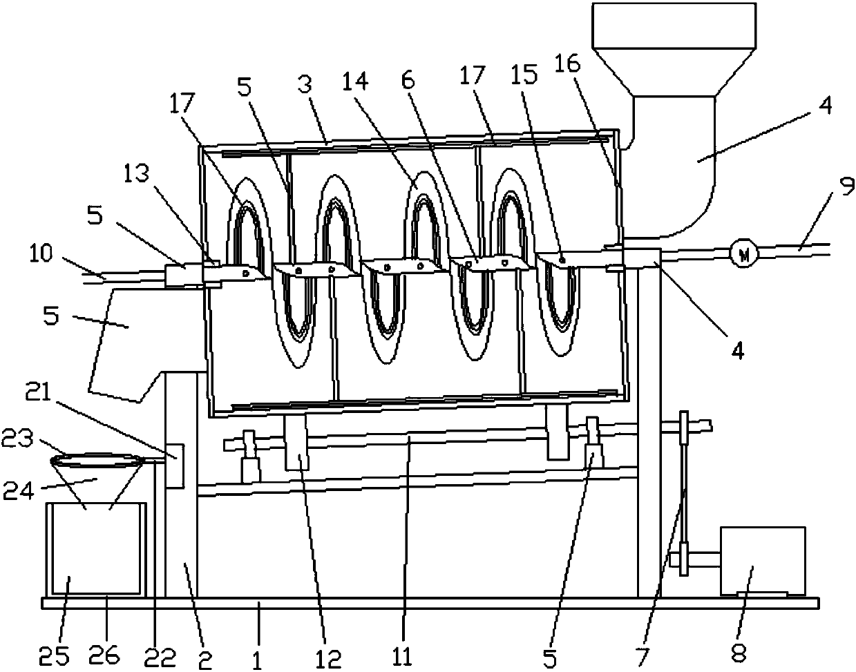
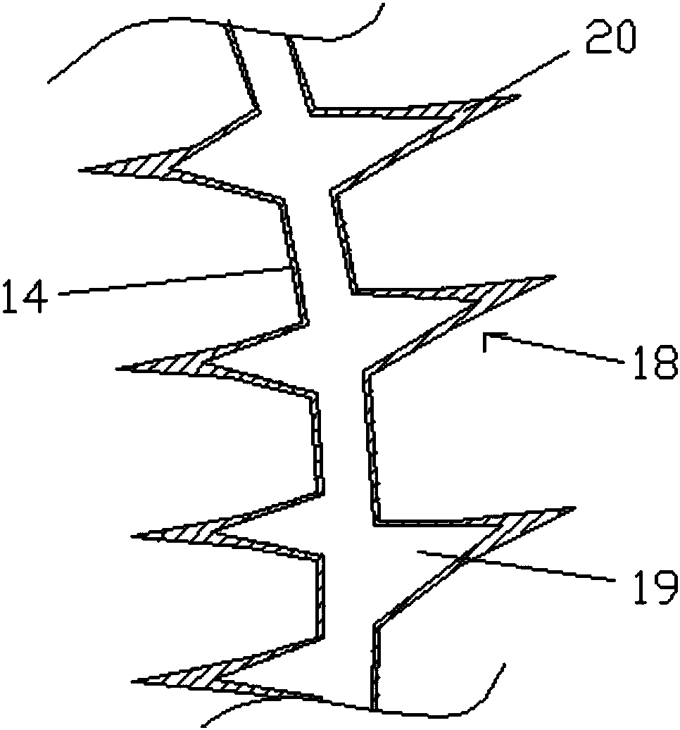
[0022] The purpose of this embodiment is to provide a drum rotating drying granulation device, such as figure 1 with figure 2 As shown, the drying and granulating device includes a base 1, a bracket 2, a rotating drum 3 and a strip scraper 17, and the two ends of the rotating drum are installed on the bracket at an angle of 20° through bearings, and the high end of the rotating drum The side is provided with a feed port 4, and the lower side of the drum is provided with a discharge port 5; the lower ends of the two supports 2 are respectively fixed on the bottom surface through the base 1; the center of the drum 3 is provided with a central axis fixed heat pipe 6. The fixed heat pipe 6 inside the drum is provided with a hollow spiral blade 14 communicating with ...


PUM

PropertyMeasurementUnit
angleaaaaaaaaaa

Abstract

The invention discloses a rotary drum rotary-type drying granulating device. The rotary drum rotary-type drying granulating device comprises a base, supports, a rotary drum and a strip-type scraping plate, wherein the two ends of the rotary drum are arranged on the supports; a feed port is formed in the side surface of the high end of the rotary drum; a discharge port is formed in the side surfaceof the low end of the rotary drum; the lower ends of the two supports are fixed on the bottom surface through the base; a center shaft fixing heat conducting pipe is arranged in the center of the rotary drum in a penetration manner; hollow helical blades communicated with the fixing heat conducting pipe are arranged on the part, inside the rotary drum, of the fixing heat conducting pipe; a plurality of hot air outlets are also formed in the fixing heat conducting pipe; the parts, outside the rotary drum, of the fixing heat conducting pipe are communicated to a steam input pipe and a steam output pipe in a sealing manner; a plurality of fins are also arranged on the helical blades along the helical direction of the helical blades; and one side of the strip-type scraping plate is leaned against the inner wall of the rotary drum, and the other side of the strip-type scraping plate is fixedly connected to the fixing heat conducting pipe by at least two supporting rods. The rotary drum rotary-type drying granulating device is simple in structure and reasonable in design, has a good drying effect and high drying efficiency and is capable of grading dried materials; and materials are less likely to bond by adopting the rotary drum rotary-type drying granulating device.

Description

technical field [0001] The invention relates to a drum rotating drying and granulating device. Background technique [0002] Existing material dryers used in the field of biomass energy recovery and reuse usually adopt an external heating method, such as using hot air to heat the inside of the drum while blowing away the humid air to achieve the purpose of drying. However, this method usually requires a higher temperature or a larger drying space to meet the drying requirements; moreover, since the steam will condense when the temperature drops, a larger hot air velocity is required to blow it away, which will cause a large amount of heat energy. waste. In addition, wet materials are easy to stick to each other or stick to the inner wall of the drum. The particles of the bonded materials are larger, and the inside is not easy to dry, and its particle size does not necessarily meet the requirements. Increase, the rotation consumes more energy, wastes materials, and increase...

Claims


Application Information

Patent Timeline
Patent Type & Authority Applications(China)
IPC IPC(8): F26B11/06F26B21/00F26B23/10F26B25/04B01J2/12B01J2/00B07B1/28
CPCB01J2/00B01J2/12F26B11/045F26B11/0481F26B21/00F26B23/10F26B25/04B07B1/28
Inventor 王馨淳
Owner 四川旭瑞达机电设备有限公司
Learn More