Movable tank type cooler and sinter cooling method

A cooling machine and mobile tank technology, applied in the field of mobile tank coolers and sinter cooling, can solve the problems that cannot meet the output requirements of sintering machines, and it is difficult to realize sinter cooling

Active Publication Date: 2018-03-13
ZHONGYE-CHANGTIAN INT ENG CO LTD
View PDF6 Cites 0 Cited by
  • Summary
  • Abstract
  • Description
  • Claims
  • Application Information

AI Technical Summary

Problems solved by technology

However, the output of the sintering machine per unit time is much larger than that of the coke oven, so the single-tank structure adopted by the CDQ furnace is

Method used


Image

  • Movable tank type cooler and sinter cooling method
  • Movable tank type cooler and sinter cooling method
  • Movable tank type cooler and sinter cooling method

Examples


Embodiment 1

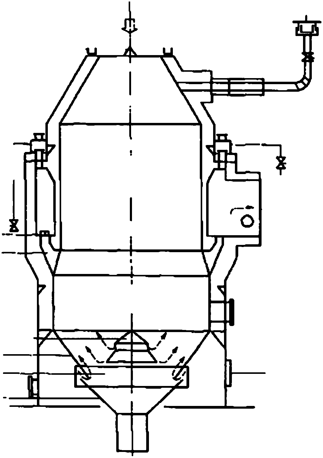
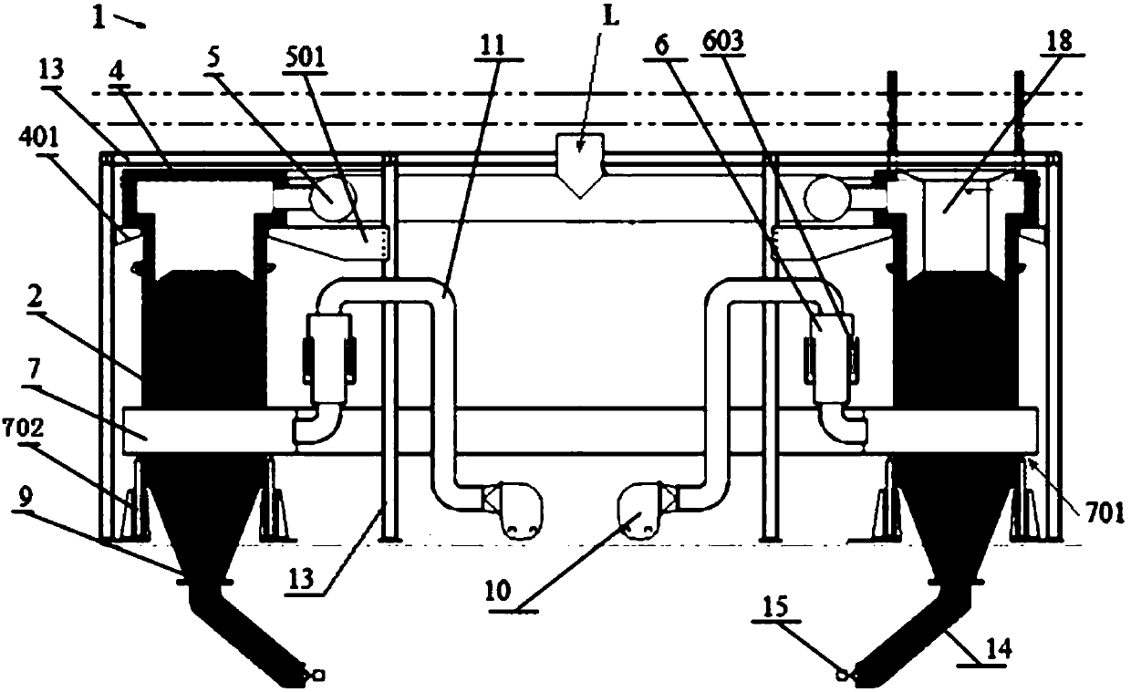
[0106] Such as figure 2 , image 3 and Figure 4, a mobile tank cooler 1, the cooler includes: the sintered ore from the sintering machine is stacked from the top of the annular groove cooling bin 2, wherein the upper part of the annular groove cooling bin 2 is provided with a feed hopper 17, and the annular groove A feed chute 18 is provided above the inner top of the shape cooling bin 2, wherein the feed hopper 17 communicates with the feed chute 18; the driving device 3 for driving the above-mentioned annular groove cooling bin to make a rotary motion in the horizontal direction; The annular hot air cover 4 provided on the trough-shaped cooling bin and covering the upper part of the above-mentioned annular trough-shaped cooling bin, the hot-air cover sealing device 19 is arranged between the annular trough-shaped cooling bin 2 and the hot-air cover 4; it is connected to the top of the above-mentioned hot-air cover 4 4 hot air collecting pipes 5, the hot air collecting pi...

Embodiment 2

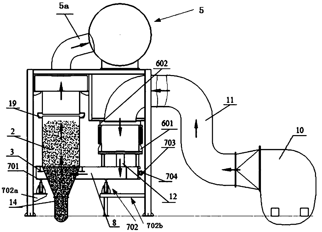
[0109] Such as Figure 5 and Figure 6 As shown, embodiment 1 is repeated, except that the cooling air duct 6 is arranged outside the annular groove-shaped cooling bin 2 .

Embodiment 3

[0111] Repeat embodiment 1, just change the first mine row device 15 into the second mine row device 16. Such as Figure 8 , the second ore discharge device 16 includes a hanging seat 1601, a hanging sleeve 1602, a second control wheel 1603, an anti-blocking groove 1604, a lifting track 1605, a second counterweight 1606 and a second discharge door 1607, wherein the lifting track 1605 Set at the exit of the unloading section, the entrance of the unloading section is provided with a bumper, the second unloading door 1607 is vertically set on the lower edge of the ore discharge pipe 14, and the hanging seat 1601 is installed on the ore discharge pipe 14 the upper edge of the nozzle, the hanging sleeve 1602 is arranged on the upper part of the second discharge door 1607, the second control wheel 1603 is installed on the middle part of the second discharge door 1607, and the second counterweight 1606 is arranged on the second discharge door 1607 In the lower part, the anti-blockin...


PUM


Abstract

The invention discloses a movable tank type cooler. The cooler comprises 1) a ring-groove-shaped cooling bin, 2) a drive device driving the ring-groove-shaped cooling bin to move, 3) an annular hot air cover arranged on the ring-groove-shaped cooling bin, 4) at least one hot air collecting pipe connected to the top or the side portion of the hot air cover, 5) a cooling air flue arranged on the inner side of the ring-groove-shaped cooling bin, 6) an annular rotation rack arranged at the bottoms of the ring-groove-shaped cooling bin and the cooling air flue, 7) an ore discharging bucket arrangedat the lower portion of the ring-groove-shaped cooling bin, 8) a plurality of cooling draught fans and 9) a cooling air communication pipe. The cooling air flue comprises a cooling air flue moving base and a cooling air flue fixing cover. An air passing beam is arranged in the annular rotation rack in a hollow manner. Air outlets of the cooling draught fans communicate with the cooling air flue through cooling air pipes corresponding to the cooling draught fans. The cooling air communication pipe is arranged between the cooling air flue moving base and the annular rotation rack. According tothe movable tank type cooler, all air leakage links are eliminated, good sealing performance of movable tank cooling is guaranteed, and the waste heat recycling amount is greatly increased.

Description

technical field [0001] The invention belongs to the fields of ironmaking and environmental protection, and in particular relates to a mobile tank cooler and a sinter cooling method. Background technique [0002] Powdered iron ore concentrate powder must be agglomerated before entering the blast furnace. The sintering process is the main process for iron ore agglomeration in the iron and steel industry. The discharge temperature of the sintered ore is generally 600°C to 700°C. After cooling, the hot ore enters the raw material warehouse for standby, and the temperature of the cooled sintered ore does not exceed 150°C. Due to the huge output of sinter ore, the domestic annual iron production is calculated as 800 million tons, and the annual production of sinter ore exceeds 1.7 billion tons. It can be seen that the heat energy released during the cooling process of sinter ore is very considerable. [0003] At the end of the last century, with the development of technology and ...

Claims


Application Information

Patent Timeline
IPC IPC(8): F27D15/02F27D17/00
CPCF27D15/0286F27D17/004F27D2015/0293
Inventor 刘克俭戴波温荣耀
Owner ZHONGYE-CHANGTIAN INT ENG CO LTD
Why Eureka
Try Eureka