
Magnetic-field-based deep deformation instability monitoring system of slide slope and monitoring method based on the same

A monitoring system and magnetic field technology, applied in the field of measurement, can solve problems such as difficult service, complex algorithm, cumbersome instrument layout, etc.

Inactive Publication Date: 2018-03-13
SOUTHWEST UNIVERSITY
View PDF4 Cites 6 Cited by
  • Summary
  • Abstract
  • Description
  • Claims
  • Application Information

AI Technical Summary

Problems solved by technology

[0004] Aiming at the deficiencies in the existing technology, the technical problem to be solved by the present invention is to provide a magnetic field-based deep deformation and instability monitoring system and monitoring method of the slope, which overcomes the cumbersome instrument layout and difficulty in monitoring the deep deformation of the slope. Serving in harsh wild environments and related algorithms are more complicated

Method used


Image

  • Magnetic-field-based deep deformation instability monitoring system of slide slope and monitoring method based on the same
  • Magnetic-field-based deep deformation instability monitoring system of slide slope and monitoring method based on the same
  • Magnetic-field-based deep deformation instability monitoring system of slide slope and monitoring method based on the same

Examples


Embodiment 1

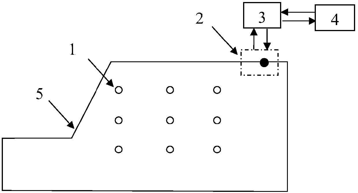
[0054] This embodiment is a magnetic field-based deep deformation and instability monitoring system for slopes, such as figure 1 As shown, the monitoring system includes a magnetic field emitting element 1 , a partial tensor magnetic gradiometer 2 , a data transmission system 3 and a data control system 4 .

[0055] Among them: the number of magnetic field emitting elements 1 is multiple, buried in different measuring points inside the slope, and emit magnetic fields at their respective measuring points; part of the tensor magnetic gradiometer 2 is set on the surface of the slope and measures the magnetic field of each measuring point For the partial magnetic field gradient tensor emitted by the transmitting element 1, the number of partial tensor magnetic gradiometers 2 is not less than three, and at least three partial tensor magnetic gradiometers 2 are not collinear; the data transmission system 3 converts the magnetic field gradient tensor The data is transmitted to the da...

Embodiment 2

[0061] The present embodiment is the monitoring method of the present invention, comprises the following steps:

[0062] S1) Arrange several measuring points in the slope, and bury a magnetic field emitting element in each measuring point; select n reference points (n≥3) on the slope surface, and at least three reference points are not collinear, and each Arrange a partial tensor magnetic gradiometer at each reference point to measure the partial magnetic field gradient tensor of the magnetic field emitting element at each measuring point in the slope, select one of the reference points as the coordinate origin O during monitoring, and define the monitoring coordinates In the Oxyz system, the z-axis direction must be vertically upward, the x-axis direction and the y-axis direction must be consistent with the x-axis direction and the y-axis direction of the partial tensor magnetic field gradient sensor. Under the monitoring coordinate system Oxyz, measure the three-dimensional ...


PUM


Abstract

The invention provides a magnetic-field-based deep deformation instability monitoring system of a slide slope and a monitoring method based on the same so as to meet an urgency need of deep deformation instability monitoring of the slide slope. The monitoring system having advantages of good concealment performance, high adaptability, and good interference prevention property is easy to repair andis capable of monitoring the large deformation in the middle and later periods of the side slope. The monitoring method is carried out simply; three-dimensional positioning of the magnetic field emission element embedded in the slope is realized under the circumstance that the parts of magnetic field gradient parameters are obtained only by measurement, so that the deep deformation of the side slope is monitored precisely. Therefore, the deformation instability monitoring of the slide slope is realized.

Description

technical field [0001] The invention belongs to the technical field of measurement, and in particular relates to a monitoring system and a monitoring method for deep deformation and instability of a slope based on a magnetic field. Background technique [0002] Slope deformation is a gradual process: sliding instability gradually expands and evolves from deep deformation to the surface forming a sliding surface. When the slope is close to instability and failure, it presents sudden change and randomness. Therefore, the deep deformation monitoring of the slope is particularly important. At present, the deep deformation monitoring equipment and methods of slope mainly include borehole inclinometer, sliding micrometer, multi-point displacement meter, electromagnetic wave time domain reflectometry (Time domain reflectometry, TDR), etc., among which borehole inclinometer, sliding micrometer However, the electromagnetic wave time-domain reflectometry technology can only determine...

Claims


Application Information

Patent Timeline
IPC IPC(8): G01B7/16G01B7/24
CPCG01B7/16G01B7/24
Inventor 江胜华刘晓春宋韫皓孙伟贺姚捷
Owner SOUTHWEST UNIVERSITY
Learn More