Periodic gradual change raster display waveguide and manufacturing method and application thereof

A technology of grating display and manufacturing method, applied in the direction of light guide, diffraction grating, optics, etc., can solve the problems of low accuracy and efficiency, limited field of view, burrs, etc., and achieves correction of off-axis large field of view aberration, High precision and diffraction efficiency, the effect of large field of view

Active Publication Date: 2018-03-13
LIGHTIN INC
View PDF6 Cites 9 Cited by
  • Summary
  • Abstract
  • Description
  • Claims
  • Application Information

AI Technical Summary

Problems solved by technology

Gradation can improve the field of view limitation of traditional ungraded grating waveguide, but it also has certain disadvantages: (1) It uses interference fringes to develop and shape, the edges are not clear, there will be burrs, and the accuracy and efficiency will be much lower; ( 2) The period and inclination angle of the grating stripes change monotonously and continuously, which is difficult to achieve continuous change in actual production, which will lead to low diffraction efficiency and limited field of view

Method used


Image

  • Periodic gradual change raster display waveguide and manufacturing method and application thereof
  • Periodic gradual change raster display waveguide and manufacturing method and application thereof
  • Periodic gradual change raster display waveguide and manufacturing method and application thereof

Examples


Embodiment 1

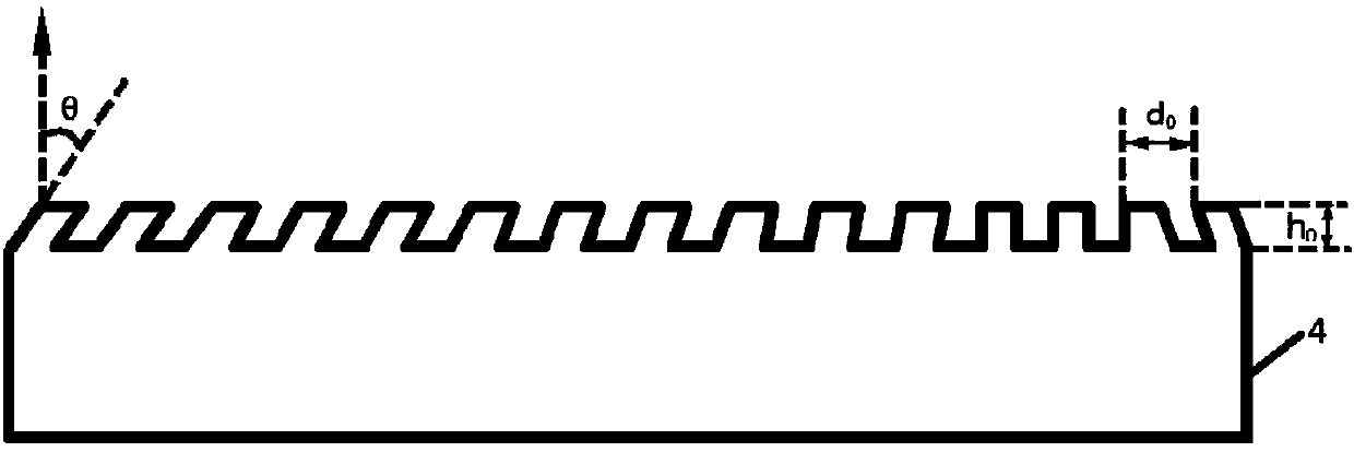
[0043] combine Figure 1-Figure 4 , this embodiment describes in detail the periodic gradient grating display waveguide of the present invention, as figure 1 As shown, it includes: a front surface and a rear surface, a grating structure is arranged on the front surface, and the period and inclination angle of the grating structure are discretely changed at the pixel level along the horizontal direction. The grating structure of this embodiment has an inclined relief grating, the number of inclined relief gratings matches the number of image source pixels, each pixel corresponds to a specific inclined relief grating, and the inclination angle and side length ( That is, the corresponding grating periods) are different. Such as figure 1 As shown, the grating display waveguide in this embodiment is in the shape of a cuboid, the embossed grating surfaces are arranged in the horizontal direction, and the grating period and inclination angle θ gradually change. Such as figure 2 ...

Embodiment 2

[0047] This embodiment describes in detail the manufacturing method of the periodic gradient grating display waveguide of the present invention, which includes the following steps:

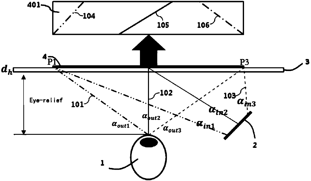
[0048]S11: According to the required Eye-relief, combined with the parameters n and d of the base material h Calculate each α in the field of view of the human eye out The exit position P of the light on the grating waveguide;

[0049] P i =f(Eye-lelief,n,d h , α outi ) i=1, 2, 3...;

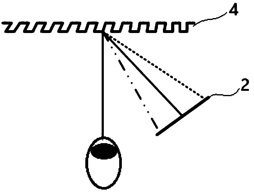
[0050] S12: The image source on the microdisplay corresponds to the display waveguide on the pixel, such as Figure 4 As shown, the incident ray angle α of a certain pixel point A on the microdisplay in , Corresponding to the exit ray angle α of point P on the waveguide out , the inclination angle θ of the grating at position P can be calculated from the geometric relationship;

[0051]

[0052] S13: According to the incident light angle α of each field of view in , Angle of outgoing light α out , the e...


PUM


Abstract

The invention discloses a periodic gradual change raster display waveguide and a manufacturing method and application thereof. The waveguide comprises a front surface and a rear surface, and the frontsurface is provided with a raster structure. The period and inclination angle of the raster structure changes at a pixel level in a horizontal direction in a discrete manner. The manufacturing methodcomprises the steps: calculating an emergent position of light on the raster waveguide; calculating a raster inclination angle; calculating a raster period; and manufacturing the periodic gradual change raster display waveguide according to all parameters. The application is used for color display, and comprises a plurality of periodic gradual change raster display waveguides which are sequentially overlapped. The application is also used for an extended exit pupil, and comprises a plurality of periodic gradual change raster display waveguides, wherein each two adjacent periodic gradual change raster display waveguides are separated by the size of one exit pupil. According to the invention, the periodic gradual change raster display waveguide is high in precision and diffraction efficiency, is clear in contour, and can achieve a big view field angle.

Description

technical field [0001] The present invention relates to the technical field of grating waveguide display, in particular to a period-gradient grating display waveguide and its manufacturing method and application. Background technique [0002] Due to the angle and wavelength selectivity of the grating waveguide, the traditional non-gradient grating waveguide, the entire grating surface only produces high diffraction for one incident angle of one wavelength. Generally, it is difficult to obtain a large angular bandwidth while obtaining a high diffraction rate. [0003] In order to solve the above problems, a graded volume holographic grating has been proposed, which records grating stripes on a holographic recording material, and the period and inclination angle of the grating stripes change monotonously and continuously. Gradation can improve the field of view limitation of traditional ungraded grating waveguide, but it also has certain disadvantages: (1) It uses interference...

Claims


Application Information

Patent Timeline
Patent Type & Authority Applications(China)
IPC IPC(8): G02B6/124G02B5/18
CPCG02B5/1842G02B6/124
Inventor 许江华张卓鹏魏一振
Owner LIGHTIN INC
Why Eureka
Try Eureka