
Composite type high-speed permanent magnet motor rotor and manufacturing method therefor
A technology of permanent magnet motor and manufacturing method, which is applied in the manufacture of motor generators, magnetic circuit rotating parts, stator/rotor bodies, etc., which can solve the problems of low manufacturing efficiency, difficult assembly, complicated manufacturing process, etc., and achieve the reduction of material And manpower waste, simple assembly, high precision effect
- Summary
- Abstract
- Description
- Claims
- Application Information
AI Technical Summary
Problems solved by technology
Method used
Image

Examples
Embodiment 1
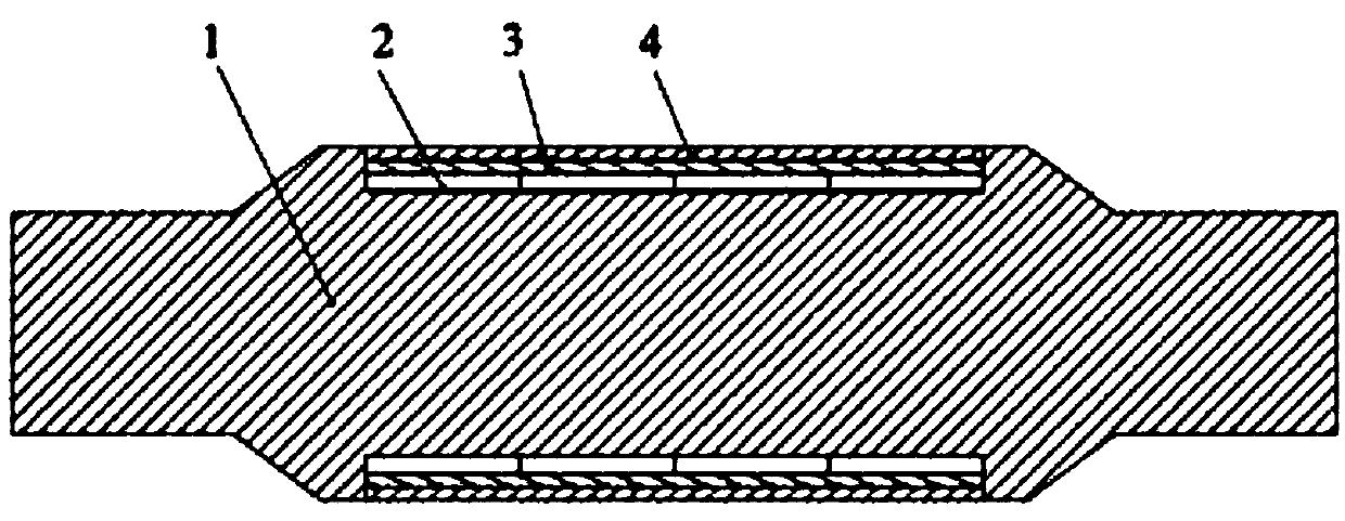
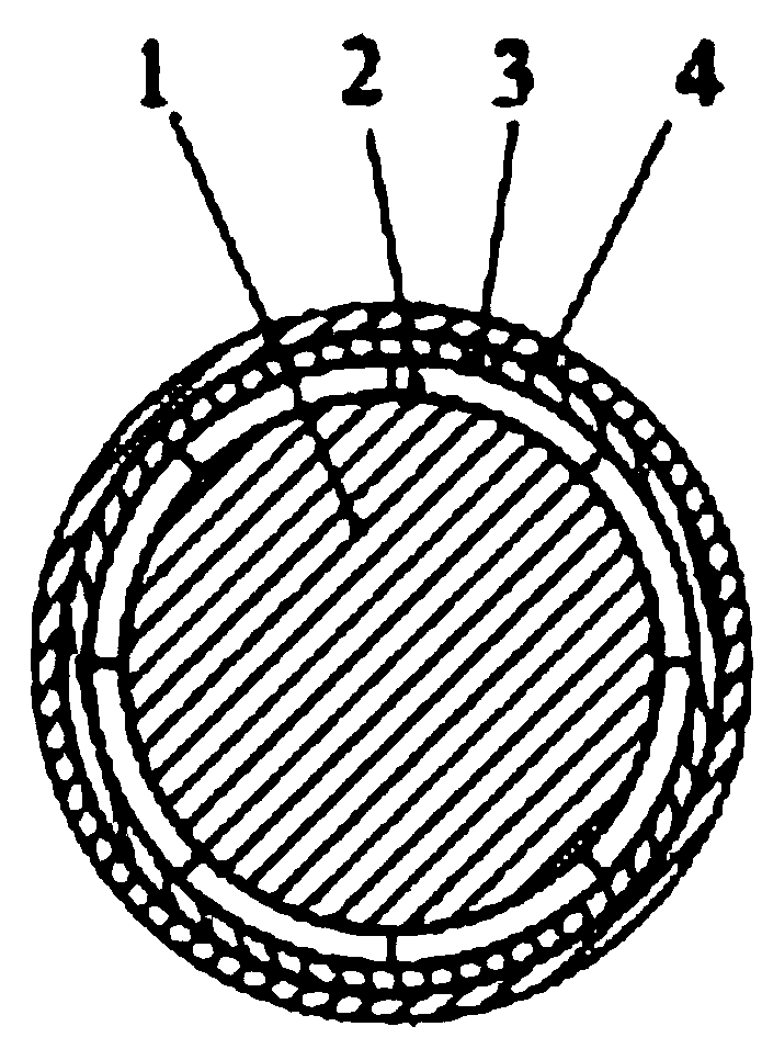
[0040] like figure 2 , 3 As shown, this embodiment discloses a method for manufacturing a rotor of a composite high-speed permanent magnet motor, and a product produced according to the method. The steps of its production are as follows:
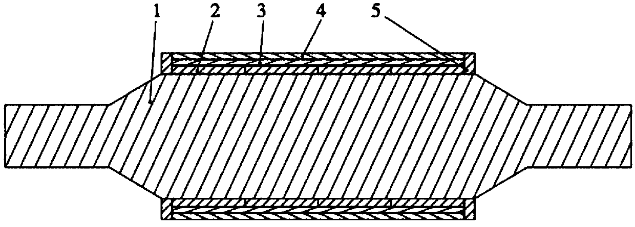
[0041] The shaft 1 is made of magnetically conductive material. In this embodiment, No. 45 steel is used. figure 2 The structure shown in , there is a concave part in the middle, and bosses are left on both sides, and its function is the same as that of the end plate 5 in the prior art (such as figure 1 ), which can block the left and right movement of the middle part, which is very important for high-speed rotating structures.
[0042] In this solution, the permanent magnet block 2 is composed of several small permanent magnet blocks, and the small permanent magnet blocks are arc-shaped structures, and the number in the circumferential direction and the axial direction is pasted according to the requirements. The permanent magnet bloc...
PUM
| Property | Measurement | Unit |
|---|---|---|
| thickness | aaaaa | aaaaa |
| thickness | aaaaa | aaaaa |
Abstract
Description
Claims
Application Information