Tool rest structure for machine tools

A tool holder and machine tool technology, applied in the mechanical field, can solve the problems of difficult to guarantee the machining accuracy of the workpiece, the tool does not have the precise adjustment function, and the tool service life is reduced, and the effect of optimizing the tool turning performance, simple structure and improving the service life is achieved.

Pending Publication Date: 2018-03-20
TAIZHOU EASTERN CNC EQUIP CO LTD
View PDF0 Cites 0 Cited by
  • Summary
  • Abstract
  • Description
  • Claims
  • Application Information

AI Technical Summary

Problems solved by technology

Because the same tool is used for rough turning and finishing turning, the service life of the tool is reduced; at the same time, because the tool does not have the function of precise adjustment, it is difficult to guarantee the machining accuracy of the workpiece during the finishing process

Method used


Image

  • Tool rest structure for machine tools
  • Tool rest structure for machine tools
  • Tool rest structure for machine tools

Examples


Embodiment 1

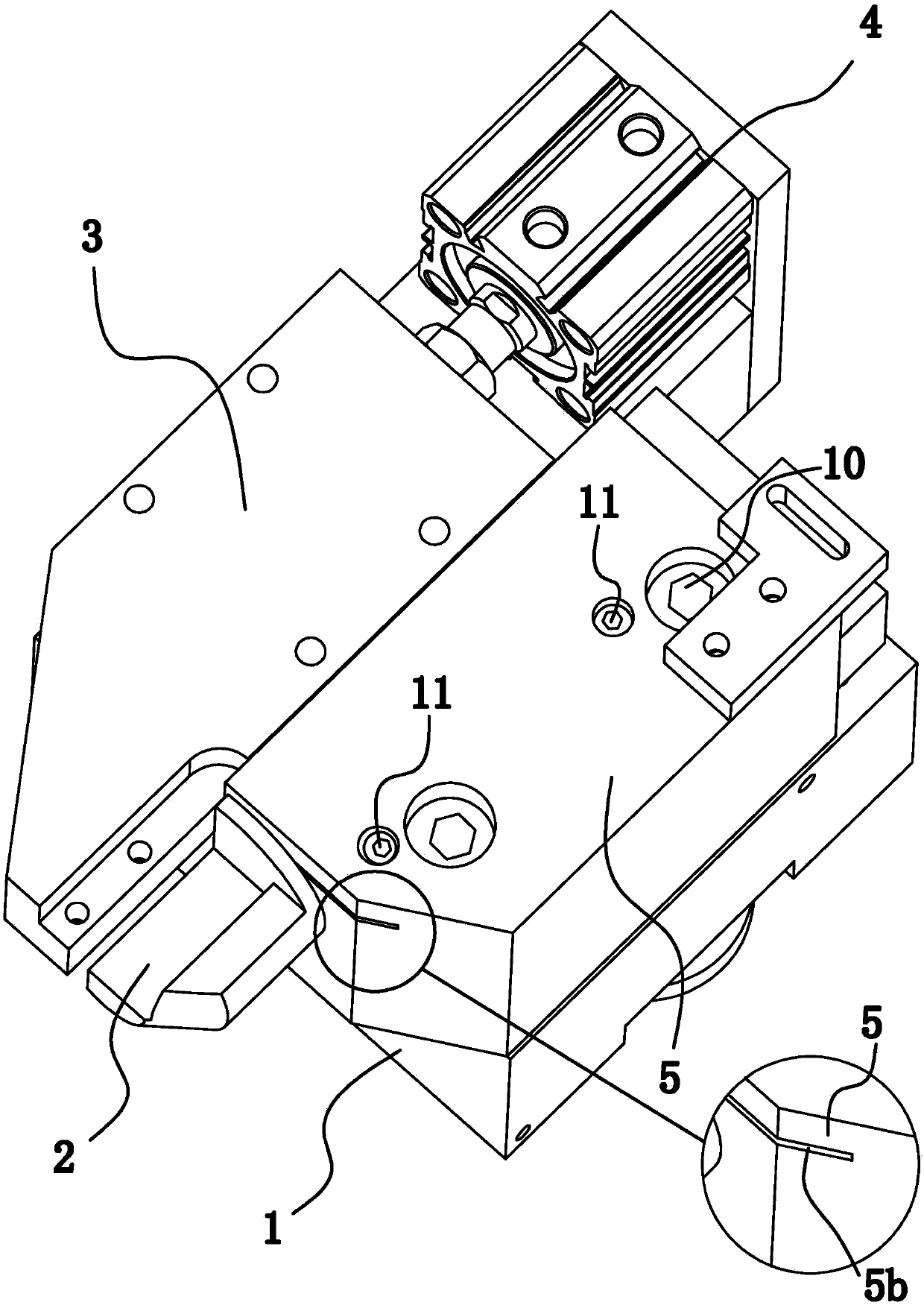
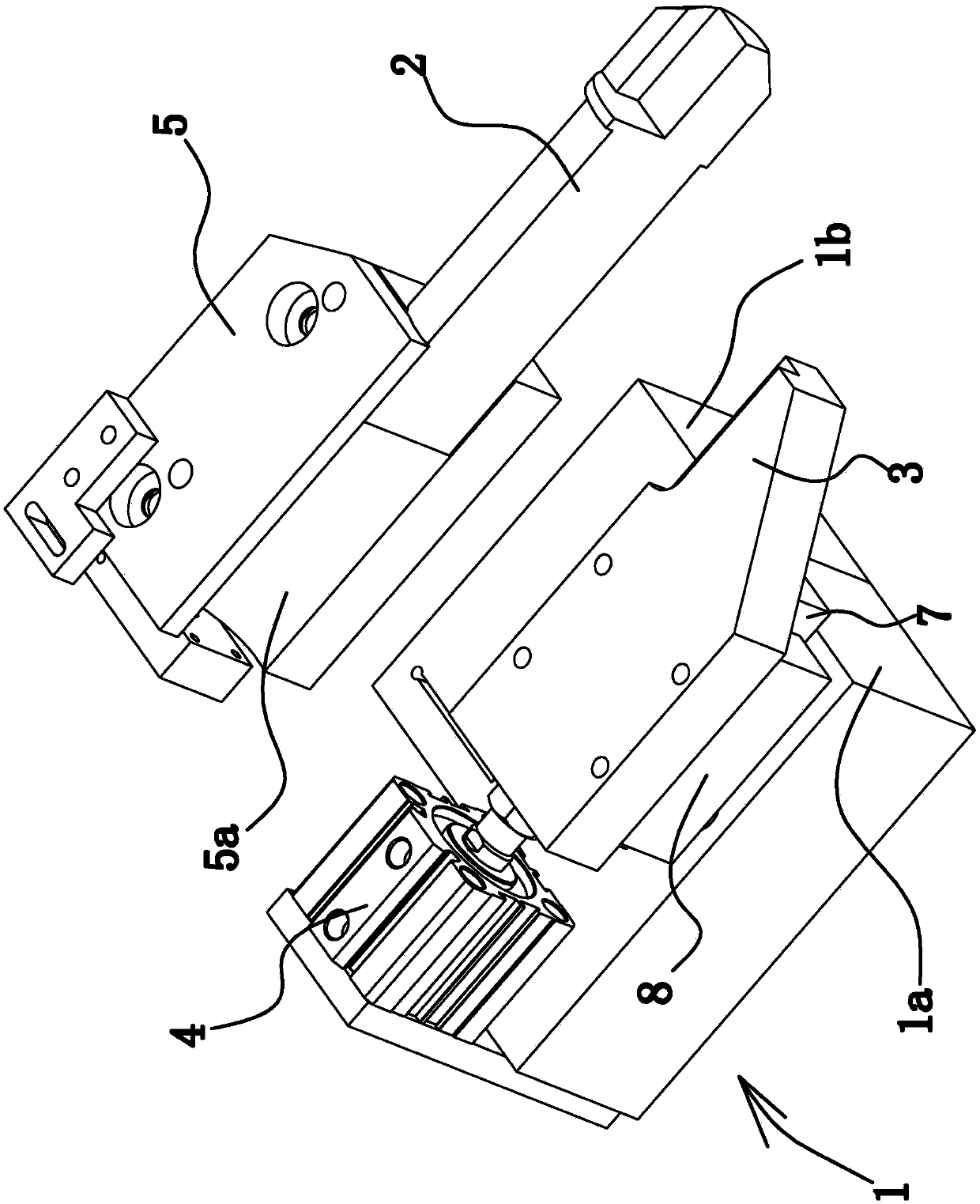
[0021] Such as Figure 1 to Figure 4 As shown, the structure of the tool holder for this machine tool is composed of a base 1, a fine tool holder 2, a rough tool holder 3, a driving part 4, an adjustment block 5, and the like. Wherein, the adjusting block 5 has elasticity, and its material can be spring steel or aluminum alloy.

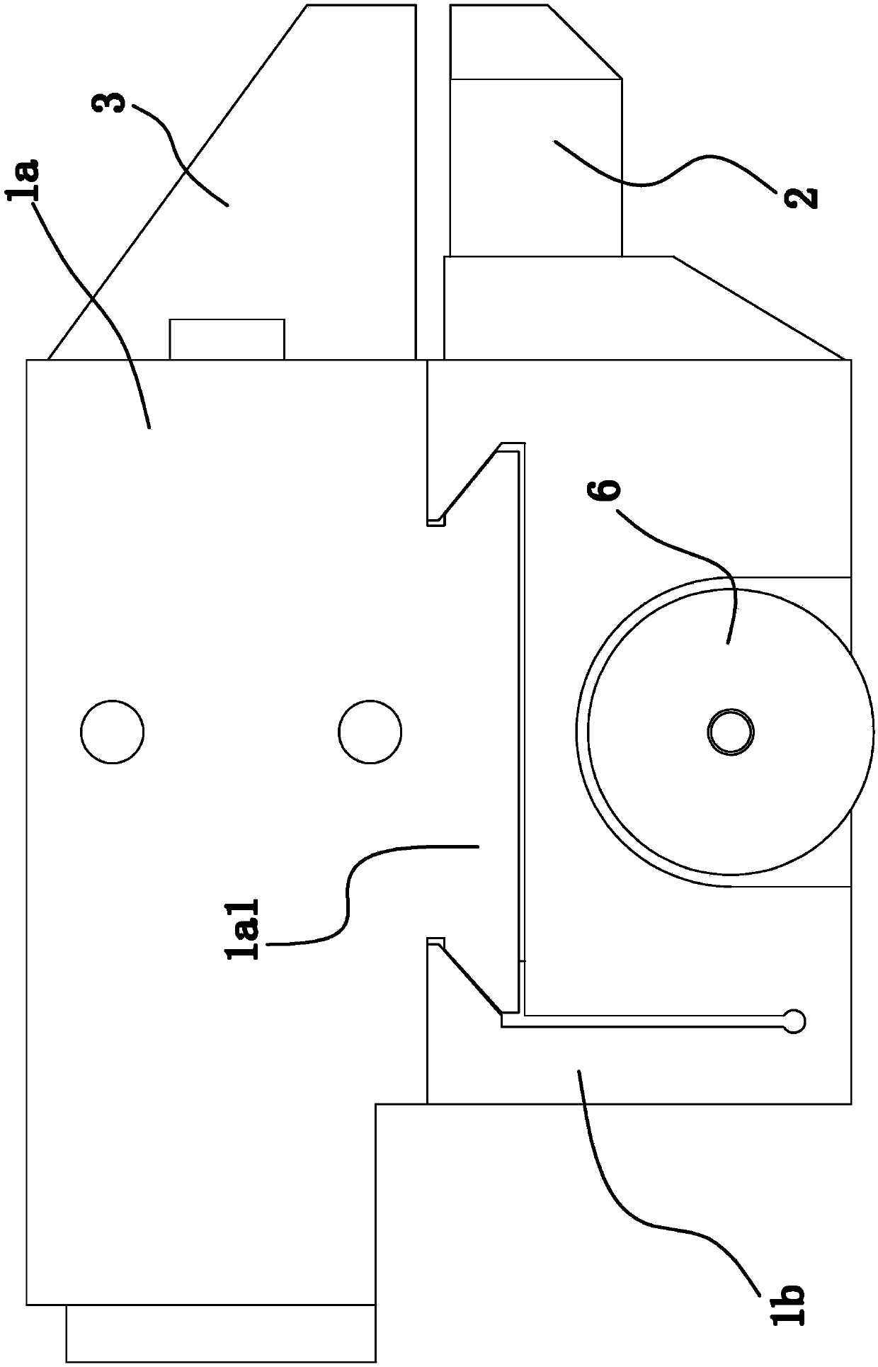
[0022] Specifically, as figure 2 with image 3 As shown, the base 1 includes a left base 1a and a right base 1b arranged side by side, wherein the right base 1b is provided with a dovetail groove along the vertical direction, and the left base 1a is correspondingly provided with a dovetail block 1a1, and the dovetail block 1a1 is located on the dovetail in the slot. During actual installation, the left base 1a is fixed on the machine bed, and with the cooperation of the dovetail block 1a1 and the dovetail groove, the right base 1b can slide up and down relative to the left base 1a. To further illustrate, the fit between the dovetail groove and th...

Embodiment 2

[0030] The structure and principle of this second embodiment are basically the same as that of the first embodiment, except that the detachable locking structure includes a through hole vertically penetrating on the upper side wall of the crushing groove 5b. A screw is provided, the lower end of the screw is fixedly connected with the lower side wall of the crushing groove 5b, the upper end of the screw extends out of the through hole, and the upper end of the screw is screwed with a nut.


PUM


Abstract

The invention provides a tool holder structure for a machine tool, which belongs to the technical field of machinery. It solves the problem that the existing knife holder cannot be adjusted. The tool rest structure of this machine tool includes a base, a fine knife rest, a rough knife rest, and a driving part that can drive the rough knife rest relative to the base to translate back and forth. The base is also fixed with an adjustment block. The fine knife rest is long. It is strip-shaped and extends along the front and rear directions of the base. The front end of the fine knife holder is used to install the fine knife, and the rear end of the fine knife holder is semi-cylindrical. Inside, the wall of the semicircular hole is provided with a strip-shaped crushing groove along the left and right direction of the base. The length of the crushing groove extends along the front and rear directions of the base and both ends of the crushing groove are open. A detachable positioning mechanism that elastically deforms the upper side wall of the groove downwards and presses the semicircular hole wall against the rear end side wall of the fine knife holder. The invention has the advantage of being able to adjust the positions of the fine knife and the rough knife.

Description

technical field [0001] The invention belongs to the technical field of machinery, and relates to a machine tool, in particular to a tool holder structure for a machine tool. Background technique [0002] The existing CNC lathes use the same cutting tool for rough turning and finishing turning, and the cutting tool does not have the function of precise adjustment, so the installation accuracy of the tool seat is required to be high. Because the same tool is used for rough turning and finishing turning, the service life of the tool is reduced; at the same time, because the tool does not have the function of precise adjustment, it is difficult to guarantee the machining accuracy of the workpiece during the finishing process. Contents of the invention [0003] The purpose of the present invention is to solve the above-mentioned problems in the existing technology, and propose a tool holder structure for machine tools, and solve the technical problem of how to improve cutting p...

Claims


Application Information

Patent Timeline
Patent Type & Authority Applications(China)
IPC IPC(8): B23B21/00
CPCB23Q1/25
Inventor 赵玲刚
Owner TAIZHOU EASTERN CNC EQUIP CO LTD
Why Eureka
Try Eureka