Closed storage warehouse

A storage warehouse, closed technology, applied in the direction of loading/unloading, storage devices, conveyor objects, etc., can solve the problems of increased civil construction costs, large civil construction investment, increased load on the roof of the warehouse, etc., to reduce construction costs, The effect of simplifying the structure of the retaining wall and high degree of equipment automation

Pending Publication Date: 2018-03-20
MCC CAPITAL ENGINEERING & RESEARCH
View PDF13 Cites 5 Cited by
  • Summary
  • Abstract
  • Description
  • Claims
  • Application Information

AI Technical Summary

Problems solved by technology

[0003] The closed material warehouse combined with the unloading truck on the top of the warehouse with an intermediate retaining wall and the semi-gantry type scraper reclaimer is a closed type of material warehouse that has been widely used by iron and steel enterprises in recent years. Its biggest advantage is that it has a large reserve and occupies an area However, the limitations of this closed warehouse are also obvious. On the one hand, a track of the half-gantry scraper reclaimer needs to be set on the retaining wall. Due to the impact of the reclaimer on the deformation of the track Requirements make the deformation of the retaining wall very high, resulting in a significant increase in civil engineering costs. Furthermore, the unloading truck and the storage belt conveyor are arranged at a high place. If they are placed under the roof of the warehouse roof, it will cause The load on the ceiling increases, and the cost increases. If it is placed on the middle retaining wall, it needs to be overhead because it needs to avoid the reclaimer's walking mechanism and walking track, and the civil construction investment is also large

Method used


Image

  • Closed storage warehouse
  • Closed storage warehouse

Examples


Embodiment Construction

[0028] In order to have a clearer understanding of the technical features, purposes and effects of the present invention, the specific implementation manners of the present invention will now be described with reference to the accompanying drawings.

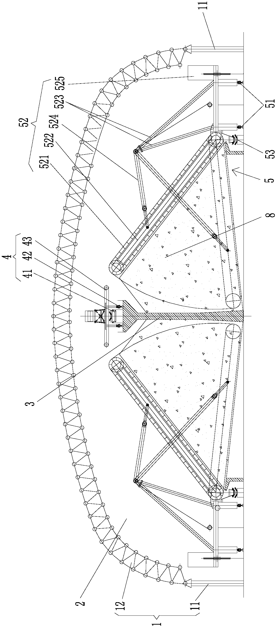
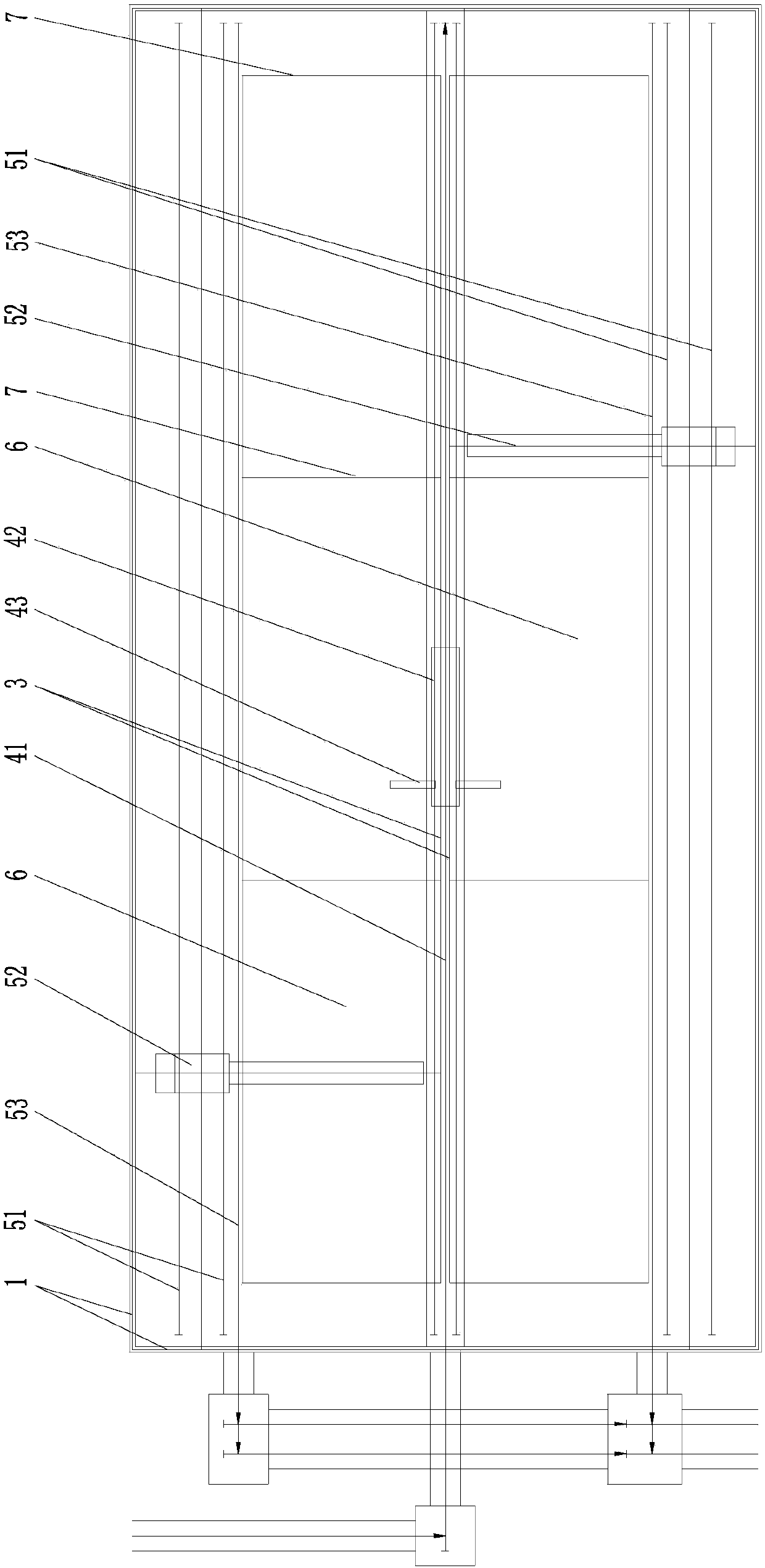
[0029] Such as figure 1 , figure 2 As shown, the present invention provides a kind of closed storage storehouse, and it has closed storehouse shell 1 (or be referred to as storehouse outer body), and closed storehouse is a single-span storehouse or is made up of a plurality of single-span storehouses. A multi-span material warehouse composed of connections, each single-span material warehouse includes a stockyard 2 located in the shell of the warehouse 1, a retaining wall 3 (or called an intermediate retaining wall) located in the stockyard 2, and a material input system 4 And the material output system 5, that is, the retaining wall 3, the material input system 4 and the material output system 5 are all located in the stockyar...


PUM


Abstract

The invention provides a closed storage warehouse. The closed storage warehouse is provided with a closed warehouse shell and is a single-span warehouse or a multi-span warehouse which is formed by connecting a plurality of single-span warehouses, and each single-span warehouse comprises a material field positioned in the warehouse shell, a retaining wall, a material input system and a material output system, wherein the retaining wall, the material input system and the material output system are arranged in the material field, the retaining wall is erected on the ground of the material field,and the material input system is arranged at the top of the retaining wall and comprises a warehouse entering belt conveyor, a discharging trolley advancing track and a discharging trolley which is arranged on the discharging trolley advancing track and connected with the warehouse entering belt conveyor; and at least one side of each retaining wall is provided with the corresponding material output system, and each material output system is separated from the retaining wall and comprises a reclaimer advancing track arranged on the ground of the corresponding material field, a scraper reclaimer arranged on the reclaimer advancing track and an ex-warehouse belt conveyor arranged on the ground of the material field and connected with the scraper reclaimer. According to the closed storage warehouse, the requirement of the scraper reclaimers for the deformation of the retaining wall can be eliminated, the retaining wall structure is simplified, and the construction cost is reduced.

Description

technical field [0001] The invention relates to the field of storage and transportation of bulk materials, in particular to a closed storage warehouse. Background technique [0002] The raw materials in the outdoor storage yard are stored in the open air, causing the particles in the raw materials to scatter around, and the dust generated during the operation of the stacker and reclaimer also affects the environment of the industrial site, especially when the raw material yard is built around the city, by the rivers and lakes or by the sea. How to solve the pollution of raw material storage to the surrounding environment and avoid the impact of bad weather on the safe operation of the storage yard is the bottleneck of the development of the raw material yard; with the continuous development of large-scale and high-environmental protection in steel plants, thermal power plants, and chemical plants , and the land used per unit of output is getting smaller and smaller. How to i...

Claims


Application Information

Patent Timeline
Patent Type & Authority Applications(China)
IPC IPC(8): B65G3/04B65G65/06B65G41/02
CPCB65G3/04B65G41/02B65G65/06
Inventor 宋宝华谭晓峰徐培万吴长武
Owner MCC CAPITAL ENGINEERING & RESEARCH
Why Eureka
Try Eureka