A high-efficiency condenser and a washing machine with the condenser

A technology for condensers and washing machines, which is applied to washing machines with containers, household clothes dryers, household appliances, etc. It can solve the problems of increasing equipment complexity and the failure of the spray mechanism to operate normally, so as to avoid the decline of heat exchange efficiency and avoid Bacterial growth and the effect of improving heat exchange efficiency

Active Publication Date: 2020-06-09
QINGDAO JIAONAN HAIER WASHING MACHINE +1
View PDF7 Cites 2 Cited by
  • Summary
  • Abstract
  • Description
  • Claims
  • Application Information

AI Technical Summary

Problems solved by technology

[0007] The sprayer of the present invention is located between the filter screen and the condenser, and a sensor is installed, which increases the complexity of the equipment, and when the sensor fails, the spray mechanism will not work normally

Method used


Image

  • A high-efficiency condenser and a washing machine with the condenser
  • A high-efficiency condenser and a washing machine with the condenser
  • A high-efficiency condenser and a washing machine with the condenser

Examples


Embodiment 1

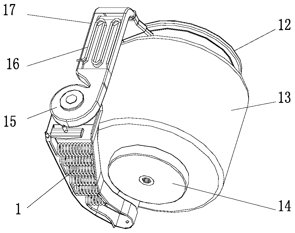
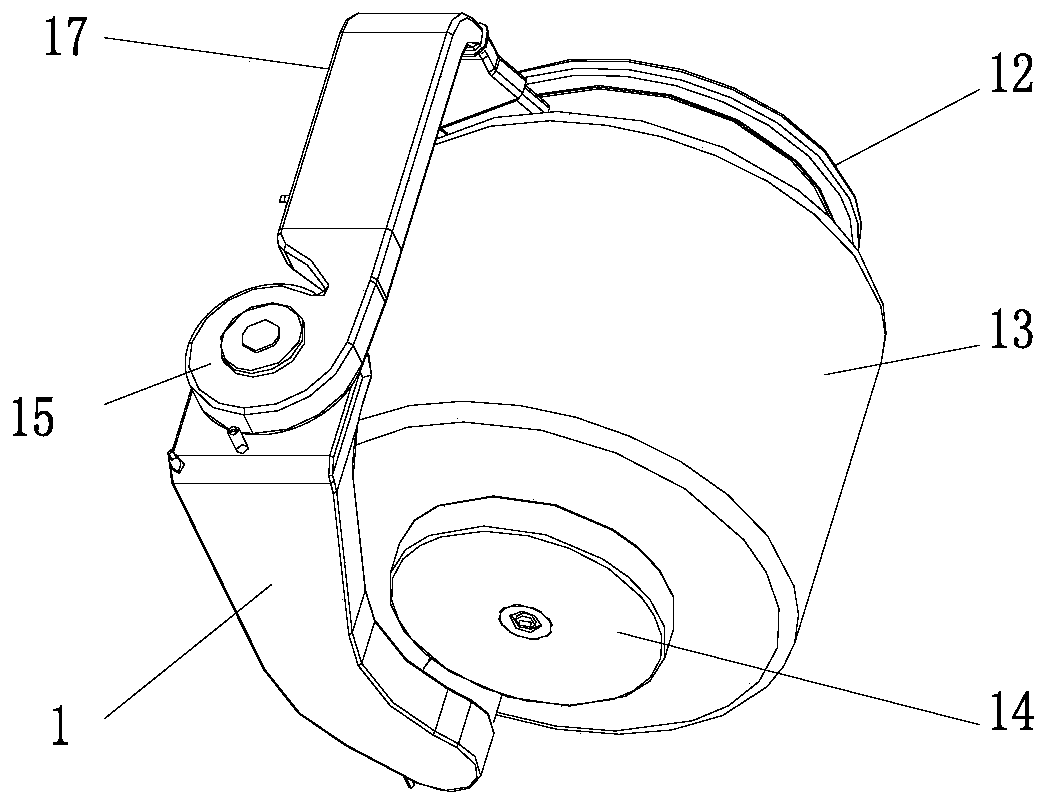
[0044] Such as Figure 1 to Figure 5 As shown, the high-efficiency condenser 1 in this embodiment is applied to a washing and drying machine. The condenser 1 is a cavity structure with a wide top and a narrow bottom, and the lower part is bent to one side, including:

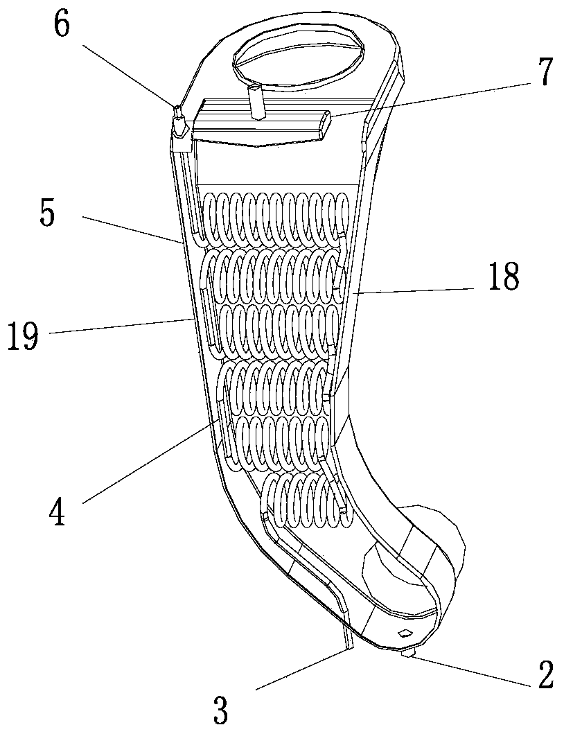
[0045] The shell 5 has an air inlet 8 on the lower part to connect with the washing machine outer cylinder 13, and an air outlet 9 on the top to connect with the fan 15 in the drying air duct 17, and the side where the curvature radius of the lower part is located is the inner side 18. The side with the larger radius of curvature is the outer side 19;

[0046] The heat exchange tube 4 is arranged in the shell 5 to exchange heat with the hot and humid air. It is hollow and wound into multiple rows of cylindrical spring-shaped heat exchange tubes arranged in multiple rows up and down. The liquid inlet 6 of the heat exchange tube 4 is located at the condensation The upper end of the condenser 1 is connected to the...

Embodiment 2

[0058] The difference between this embodiment and Embodiment 1 is that the pitch of the cylindrical spring-shaped heat exchange tubes 4 in the same line remains unchanged, the thickness of the heat exchange tubes remains unchanged, and the outer diameter of the heat exchange tubes gradually decreases from the outer side 19 to the inner side 18 .

[0059] Although the pitch of the cylindrical spring-shaped heat exchange tubes is not changed by adopting such a distribution mode of the heat exchange tubes 4, since the outer diameter of the heat exchange tubes 4 gradually decreases from the outer side 19 to the inner side 18, not only the cylindrical spring shape The gap between two adjacent turns of the heat exchange tube 4 near the outer side 19 is smaller than the gap between two adjacent turns of the heat exchange tube 4 on the inner side 18, so that the density of the heat exchange tube 4 near the outer side 19 is greater than The density of the heat exchange tubes on the inn...

Embodiment 3

[0062] The difference between this embodiment and the above-mentioned embodiment is that the pitch of the cylindrical spring-shaped heat exchange tubes of the heat exchange tube 4 in this embodiment remains unchanged, the outer diameter of the heat exchange tube 4 remains unchanged, and the inner diameter of the heat exchange tube 4 changes from Downlink and uplink gradually decrease.

[0063] Such as Figure 1 to Figure 5 As shown, when drying clothes, the heater 16 is used to heat the air, and the hot air is driven by the fan 15 into the washing tub and heats the residual moisture on the clothes into water vapor, and the water vapor is driven by the fan 15 along with the hot air from The air inlet 8 connected to the air outlet of the outer cylinder 13 at the lower part of the condenser 1 enters the condenser 1 . At the same time, the cooling water flows into the heat exchange tube 4 through the liquid inlet 6 on the upper part of the condenser 1 and is drained from the liqu...


PUM


Abstract

The invention discloses a high-efficiency condenser and a washing machine with the same. The condenser is of a cavity structure with a wider upper part and a narrower lower part, and the lower part isbent to one side. The condenser comprises a shell, heat exchange tubes, a spray box, and a condensed water outlet. An air inlet is formed in the lower part of the shell and is connected to an outer cylinder of the washing machine, an air outlet is formed in the top of the shell and is connected with a fan in a drying air duct, the side with a smaller curvature radius of the lower bending part isthe inner side, and the side with a larger curvature radius is the outer side; the heat exchange tubes are disposed in the shell for heat exchange with hot humid air, hollowed and wound into multiplerows of cylindrical spring-shaped heat exchange tubes arranged above and below; the spray box is disposed above the heat exchange tubes for flushing wire scraps on the heat exchange tubes; the condensed water outlet is located at the bottom of the condenser for discharging condensed water in the condenser and is connected to a drain pipe of the washing machine. The condenser and the washing machine realize gas-liquid separation of a condensing process; besides, through the setting of the change of the density, outer diameter and inner diameter of the heat exchange tubes, the heat exchange is more fully achieved and the condensing efficiency is improved, thus the drying efficiency of a washing and drying machine is improved.

Description

technical field [0001] The invention belongs to the field of washing and drying machines, and in particular relates to a high-efficiency condenser and a washing machine with the condenser. Background technique [0002] Most of the washing and drying machines on the market are cleaning appliances that use electric heat to automatically dry clothes. It is an important household appliance for areas where the air humidity is high and clothes are not easy to dry. Washing and drying machines are divided into drum type and cabinet type according to the structure, with drum type being the majority. A tumble dryer is generally composed of a cabinet, a drum system, a hot air system, a transmission and a control system; according to the way of water discharge, it can be divided into: exhaust type and dehumidification type. The air is directly discharged to the outside of the machine, and the dehumidification type is to pass the high-temperature and high-humidity air through the heat e...

Claims


Application Information

Patent Timeline
Patent Type & Authority Patents(China)
IPC IPC(8): D06F25/00D06F58/24D06F58/20
CPCD06F25/00D06F58/20D06F58/24
Inventor 李以民劳春峰
Owner QINGDAO JIAONAN HAIER WASHING MACHINE
Why Eureka
Try Eureka