Eureka AIR delivers breakthrough ideas for toughest innovation challenges, trusted by R&D personnel around the world.

Sweeper

A cleaning vehicle and vehicle frame technology, which is applied in the field of cleaning vehicles, can solve problems such as difficult cleaning, reduced dust removal efficiency, and reduced soot blowing efficiency, and achieves the effects of stable filtration efficiency, stable filtration environment, and stable air pressure

Pending Publication Date: 2018-03-20
BEIJIG TIANLUTONG TECH
View PDF12 Cites 2 Cited by
  • Summary
  • Abstract
  • Description
  • Claims
  • Application Information

AI Technical Summary

Problems solved by technology

However, in the actual use process, there are many problems in the above-mentioned soot blowing method for the filter cartridge, such as incomplete soot blowing, short service life of the filter cartridge, etc., which will be explained below
[0003] Since the adjacent pleat vanes 411 in the outer polygonal pleat structure 410 of the filter cartridge 400 form an acute-angle structure 412 with a smaller angle, dust often accumulates at the acute-angle structure 412, and in the cleaning process, it is often inevitable to inhale water. Minute moisture will make the dust at the acute angle structure 412 fix on the polygonal pleated structure 410, and it will be difficult to blow it off with high-pressure pulse gas, resulting in long-term blockage, thereby reducing the filtration efficiency of the filter cartridge 400. On the one hand, the pumping power is increased, on the other hand, the dust removal efficiency is reduced
In addition, the arrangement of the filter cartridge 400 will also cause the failure of the soot blowing part, such as image 3 , Figure 4 As shown, the arrangement of the filter cartridge 400 in the sweeper can adopt a horizontal arrangement, such as image 3 As shown, a vertical arrangement can also be adopted, such as Figure 4 As shown, when the filter cartridge 400 is arranged horizontally, the filter cartridge 400 is longer because the length of the filter cartridge 400 is longer. The gas power received by the filter cartridge 400 is weak, and the soot blowing efficiency is reduced; on the other hand, if figure 1 As shown, when the horizontally arranged filter cartridge 400 performs soot blowing, the dust located in the lower half 420 of the filter cartridge is separated from the polygonal pleat structure 410 under the action of the pulse gas, but the dust located in the upper half 430 of the filter cartridge After being detached from the polygonal pleated structure 410 under the action of the pulse gas, it reattached to the polygonal pleated structure 410 under the action of gravity, so that the soot blowing failed, and the filtration efficiency of the filter cartridge generally decreased. The ash accumulation effect attached to the filter cartridge 400 increases, and finally it is difficult to separate from the filter cartridge, causing the filter cartridge 400 to fail and need to be replaced
[0004] Moreover, when the cleaning vehicle is running on the road, it often inevitably passes through the water-logged road. At this time, the water on the ground will also contact the surface of the filter cartridge 400, and the filter cartridge 400 will be wetted, and the water will contact the surface of the filter cartridge 400. After the dust is mixed, the mesh of the filter cartridge 400 will be blocked, and it is difficult to remove it by using pulse gas, causing the filter cartridge to fail and be scrapped, resulting in high cost of use; in order to solve this problem, the gas sucked by the suction cup is used in the prior art The switching design, when entering the ground with water, the inhaled gas is directly discharged from the fan, and the gas inhaled from the dry ground is filtered through the filter cartridge. The switching is operated by human observation, which has high requirements for operators. When the operator does not switch on the wet ground, the filter cartridge 400 will be flooded and discarded. On the contrary, if it is switched on the dry ground by mistake, the air containing a large amount of dust sucked from the ground will be discharged to the surrounding environment under high pressure after passing through the fan. in, causing dust

Method used


Image

  • Sweeper
  • Sweeper
  • Sweeper

Examples


Embodiment Construction

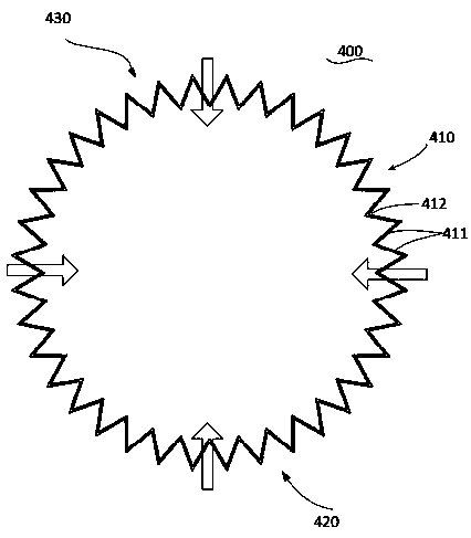
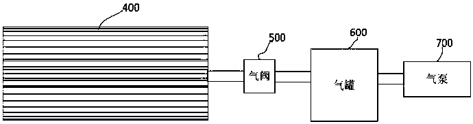
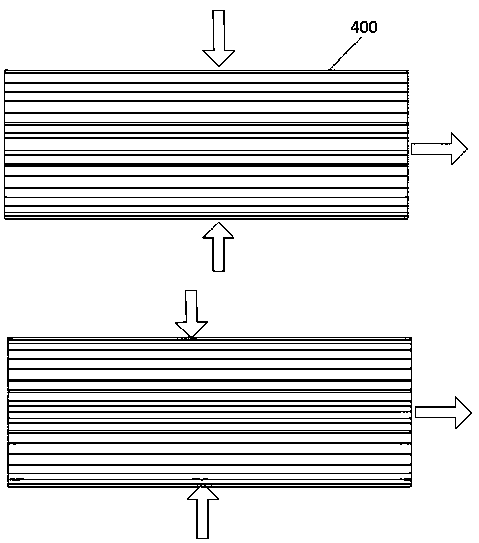
[0031] Figure 5 It is the structural representation of the cleaning vehicle of the present invention; Figure 6 It is the top view structure schematic diagram of the cleaning vehicle of the present invention; Figure 7 It is a schematic diagram corresponding to the first state (online state) in one embodiment of the airway switching device in the present invention; Figure 8 It is a schematic diagram corresponding to the second state (offline state) in one embodiment of the airway switching device in the present invention; Figure 9 It is a structural schematic diagram of another embodiment of the airway switching device in the present invention; Figure 10 It is a schematic top view structure diagram of another embodiment of the airway switching device in the present invention; Figure 11 It is a structural schematic diagram of the bag filter in the present invention; Figure 12 It is a structural schematic diagram of the water filter in the present invention; Figure 1...


PUM


Abstract

The invention relates to sweeping equipment and particularly relates to a sweeper. The sweeper comprises a frame and also comprises a box body and a fan fixed to the frame, a bag type dust collector arranged in the box body and a sucking disc arranged on the lower portion of the frame; the fan comprises an air inlet of the fan and an air outlet of the fan, and the air outlet of the fan is connected to an ash blowing port; an air flue switching device connected to a dedusting air outlet is arranged at the dedusting air outlet in the upper portion of the bag type dust collector, and the air flueswitching device is also connected to the air inlet of the fan and the ash blowing port; the air flue switching device is used for connecting the dedusting air outlet to the air inlet of the fan in afirst state and connecting the dedusting air outlet to the ash blowing port in a second state. The sweeper blows ash for a filter bag in the bag type dust collector by means of high pressure wind atthe air outlet of the fan, and is simple in structure, convenient to operate and reliable in operation.

Description

technical field [0001] The invention relates to the field of mobile cleaning equipment, in particular to a cleaning vehicle. Background technique [0002] Existing mobile dedusting equipment often causes the filter equipment in the dedusting equipment to be clogged after being used for a period of time, and regular cleaning or replacement of the filter material is required to ensure long-term effective operation of the dedusting equipment. The cleaning vehicle in the mobile dust removal equipment will block the filter cartridge in the cleaning vehicle due to absorbing dust on the road surface after cleaning the road for a period of time, and the filter cartridge needs to be cleaned regularly, or even replaced. The existing sweeper adopts the principle of direct suction dust removal, and the dust removal device uses a filter cartridge, such as figure 1 As shown, the external structure of the filter cartridge 400 is a polygonal pleated structure 410, the pre-filtered gas pass...

Claims


Application Information

Patent Timeline
Patent Type & Authority Applications(China)
IPC IPC(8): E01H1/08B01D46/02B01D46/04B01D50/00
CPCB01D46/023B01D46/04E01H1/0836E01H2001/0881B01D50/60
Inventor 杜强国施天亮
Owner BEIJIG TIANLUTONG TECH
Why Eureka
Eureka Blog
Learn More