Quickly mounted prefabricated drainage ditch

A drainage ditch, fast technology, applied in the direction of waterway system, water supply device, sewer pipeline system, etc., can solve the problems of reducing the flow rate of water, increasing the area of ​​water passing, rough inner wall, etc., and achieve rapid assembly and dismantling, installation and disassembly Convenience and reasonable structural design

Inactive Publication Date: 2018-03-20
郑州宇恒环保技术有限公司
View PDF0 Cites 1 Cited by
  • Summary
  • Abstract
  • Description
  • Claims
  • Application Information

AI Technical Summary

Problems solved by technology

Although there are drainage channels in some large construction sites, the traditional method is still used. The section design of the traditional drainage ditch rainwater channel is usually determined according to the flow requirements when the storm intensity is the largest, taking into account different rainfall intensities and flow velocities, so most of them adopt Rectangular cross-section, made of brick or concrete, this structural rainwater channel has the following disadvantages: 1. The inner wall of the brick or concrete rainwater channel is rough, and the rough surface will cause stagnation, which will not only reduce the flow rate of the water, especially when the rainfall intensity is relatively high. Hours, the liquid level in the rainwater ditch is shallow, and the water flow rate is slower, which will easily cause the pollutants on the road brought by the rainwater to deposit in the rainwater ditch, and some fibers, plastic paper, etc. will be hooked on the rough surface and have a certain surface volume. After a long period of time, the section of the rainwater channel will be greatly

Method used


Image

  • Quickly mounted prefabricated drainage ditch
  • Quickly mounted prefabricated drainage ditch
  • Quickly mounted prefabricated drainage ditch

Examples


Embodiment

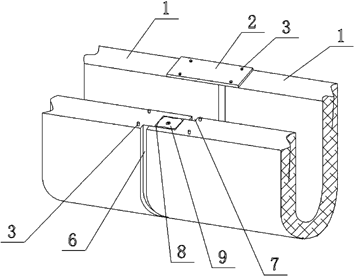
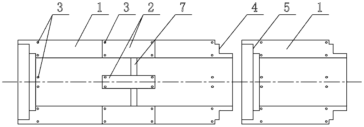
[0014] Example: such as figure 1 and figure 2 The quick-install prefabricated drainage ditch shown includes a plurality of U-shaped drainage ditch concrete unit blocks 1 which are sequentially fixedly connected by connecting plates 2 to form a combined drainage ditch. It can be quickly assembled and disassembled, and can be used repeatedly.

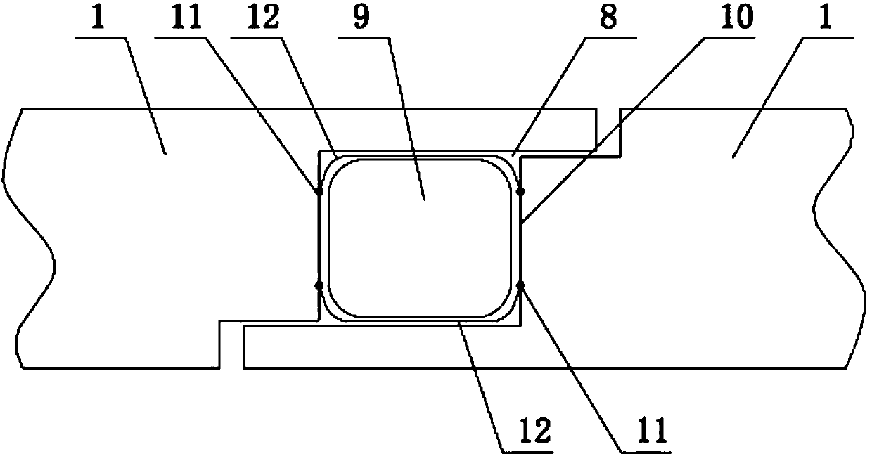
[0015] figure 1 and figure 2 It can be seen that three steps are set at one end of each U-shaped drain concrete unit block 1 to form an outer step area 4 , and three steps are set at the other end to form an inner step area 5 . Therefore, after two adjacent U-shaped drain concrete unit blocks 1 are butted, a docking reserve cavity 8 is formed between the outer step area 4 and the inner step area 5 .

[0016] Then the matching set in the docking reserved cavity 8 is equipped with an inflatable bag 9, the inflatable bag 9 contains an inflatable nozzle, and the port of the reserved cavity 8 is sealed and docked through the connecting p...

Embodiment 2

[0017] Embodiment 2: On the basis of Embodiment 1, an outer layer compensation gap is set on the outside of the butt joint surfaces of two adjacent U-shaped drain concrete unit blocks 1, and an inner layer compensation gap is set on the inside.

Embodiment 3

[0018] Embodiment 3: on the basis of embodiment 1, refer to image 3 , a pair of traction points are respectively arranged on the butt joint surfaces of two adjacent U-shaped drainage ditch concrete unit blocks at the inner end of the docking reserved cavity, and between the corresponding traction points between the adjacent two U-shaped drainage ditch concrete unit blocks Attached with leash. Setting traction points and traction belts on the butt joints of adjacent U-shaped drainage ditch concrete unit blocks can not only enhance the connection relationship, but more importantly, when two adjacent U-shaped drainage ditch concrete unit blocks move outward, through The traction belt clamps the airbag, forcing the airbag to deform, and further fits with the docking surface to prevent loose seams.


PUM


Abstract

The invention discloses a quickly mounted prefabricated drainage ditch. Three layers of steps are arranged at one end of a U-shaped drainage ditch concrete unit block to form an outer step region while three layers of steps are arranged at the other end to form an inner step region, two adjacent unit blocks are in butt joint to form a butt joint reserving cavity, and an inflating bag is assembledin the butt joint reserving cavity in a matched manner. The quickly mounted prefabricated drainage ditch disclosed by the invention can be quickly assembled and detached and repeatedly used. By arranging the inflating bag, the demand on the sealing precision of the butt joint surface of two adjacent unit bodies is not high, so that the unit bodies can be fully sealed. The quickly mounted prefabricated drainage ditch is reasonable in structural design, good in using effect and convenient to mount and detach, and can be repeatedly used. The unit pieces are standardized, so that the quickly mounted prefabricated drainage ditch is suitable for batch manufacturing and processing, can be purchased or leased to use and is suitable for being popularized and applied.

Description

technical field [0001] The invention relates to the technical field of building construction drainage devices, in particular to a quick-installation prefabricated drainage ditch. Background technique [0002] In the field of building construction, due to the special chaos of the site, many layouts are in a temporary resettlement state, so the drainage system is very simple. In case of heavy rain, the drainage will not be smooth, resulting in the construction site being muddy for a long time and unable to work normally, and the environment is very poor. Setting drainage channels on construction sites has the problems of large construction volume and inability to recycle, and the input cost is relatively high. Drainage facilities are basically not provided on many construction sites. Although there are drainage channels in some large construction sites, the traditional method is still used. The section design of the traditional drainage ditch rainwater channel is usually dete...

Claims


Application Information

Patent Timeline
IPC IPC(8): E03F3/04
CPCE03F3/046
Inventor 付玉杰王飞
Owner 郑州宇恒环保技术有限公司
Why Eureka
Try Eureka